Page 1 of 1
Messed up the wiikey fusion a bit
Posted: Sat May 09, 2015 4:50 pm
by sl33pydog
So trying to fix a single pin where one of the traces had been pulled up a bit, I tried to fix it but ending up making it worse. I think I messed up the left four pins off of the connector. Is this salvageable or lost cause?
Re: Messed up the wiikey fusion a bit
Posted: Sat May 09, 2015 4:52 pm
by sl33pydog
Oh and it looks like I melted a lot of it but when I got it there was epoxy all over that. I used smd tweezers to take off what I could.
Re: Messed up the wiikey fusion a bit
Posted: Sat May 09, 2015 9:12 pm
by Duhasst0
It could be possible to fix this.
Re: Messed up the wiikey fusion a bit
Posted: Sun May 10, 2015 1:28 am
by megalomaniac
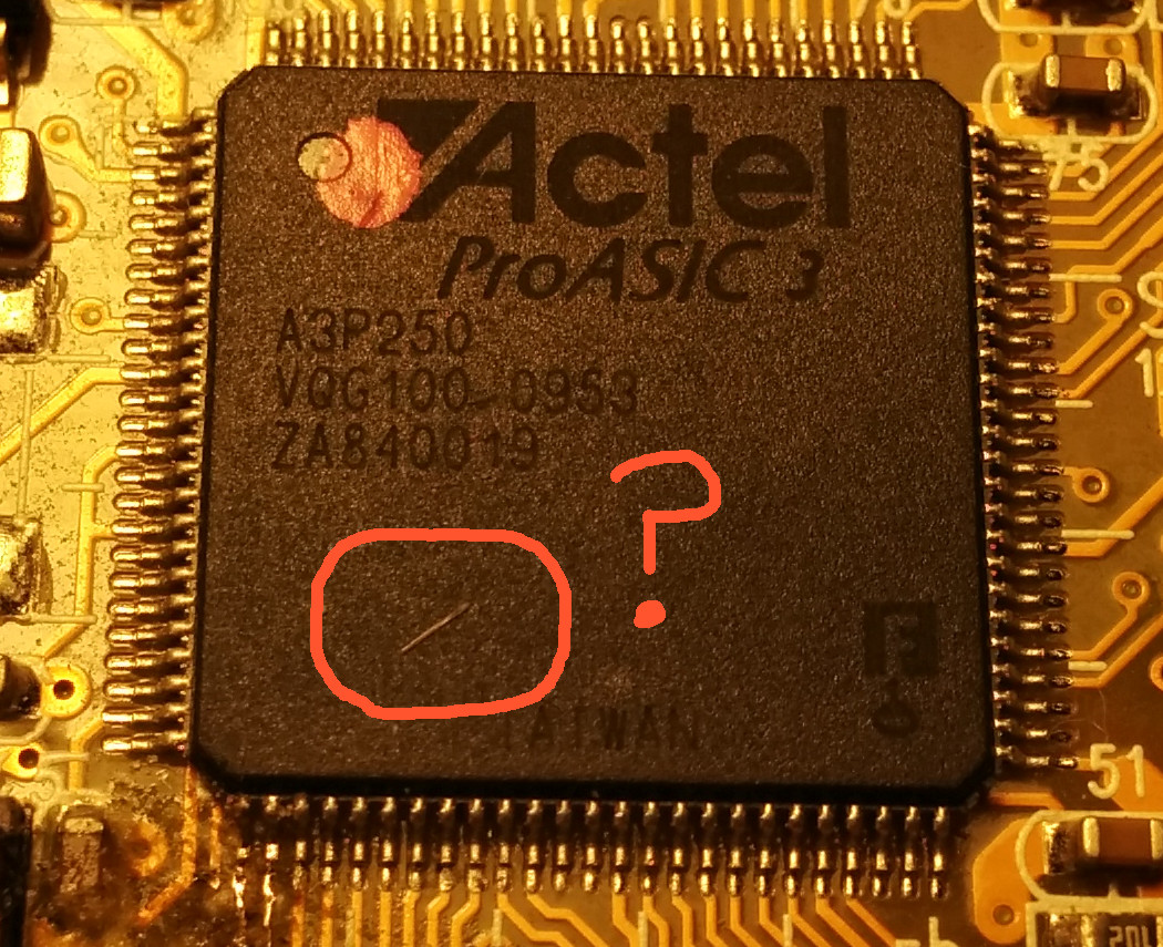
i circled a little area that looks suspicious...
can you clean that little line off or is it protruding from within the FPGA itself....
Re: Messed up the wiikey fusion a bit
Posted: Mon May 11, 2015 2:24 am
by sl33pydog
megalomaniac wrote:i circled a little area that looks suspicious...
can you clean that little line off or is it protruding from within the FPGA itself....
Turns out that was a hair. The FPGA is clean and flat.
Re: Messed up the wiikey fusion a bit
Posted: Mon May 11, 2015 3:30 am
by megalomaniac
pffffft....LOL
that hair really looks like similar to what can happen to an FPGA when it gets zapped!!
Re: Messed up the wiikey fusion a bit
Posted: Mon May 11, 2015 10:29 pm
by sl33pydog
Was that supposed to be a crack and bulge?
Re: Messed up the wiikey fusion a bit
Posted: Mon May 11, 2015 10:56 pm
by megalomaniac
no crack and buldge....something exactly like a strand of hair on top is what an FPGA can look like when a trace burns/blows
the traces are very thin wires connected to those legs and they can melt that black body with a hair line mark...
hope that explains how i was looking at it
Re: Messed up the wiikey fusion a bit
Posted: Tue May 12, 2015 1:29 pm
by sl33pydog
It does explain it.
If I wanted to run the 3.3 and ground like the picture attached, what am I attaching the 3.3 to the capacitor and the ground to the large pad that the dip switch is connected to in the corner?