Page 1 of 3
minGC Controller Board
Posted: Thu Oct 24, 2013 11:20 pm
by |RDC|
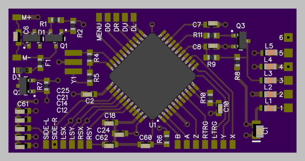
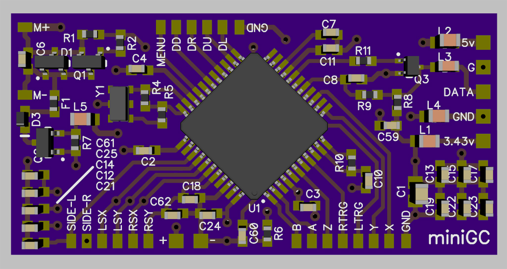
Finally finished up the core work of this mini Wired GameCube controller board. It's only a new PCB for the parts on the existing wired GC controller.
3D render of the prototype board.
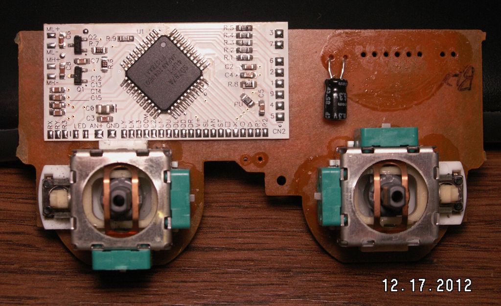
Then after it was made and most of the parts swapped over from a donor controller.
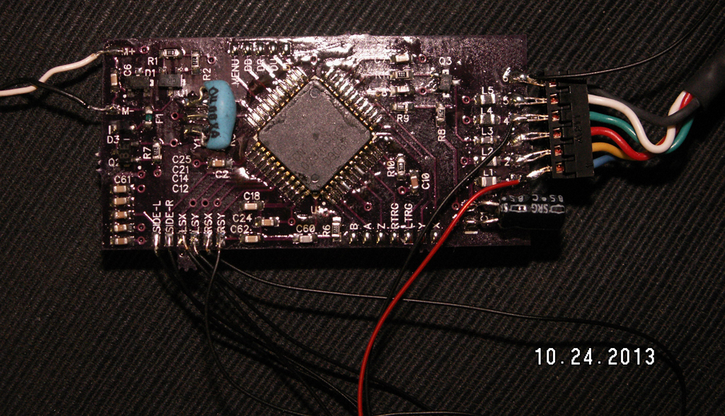
The prototype there is missing quite a few things, mostly decoupling caps, but also a couple of solder pads for the Analog voltage power and ground, couple for the Ground for the button pads and it needed a footprint change for Q3. They weren't necessary for a first run, and I was interested in getting the prototype done quickly for testing, but they have all been placed on the final revision of the PCB. The prototype there also has the larger Resonator and C1, which will be swapped out for the smaller SMT versions. Some of the wired GC controllers already have the SMT Resonator, but this one didn't.
Some Sticks, Trigger sliders and the motor wired up for testing.
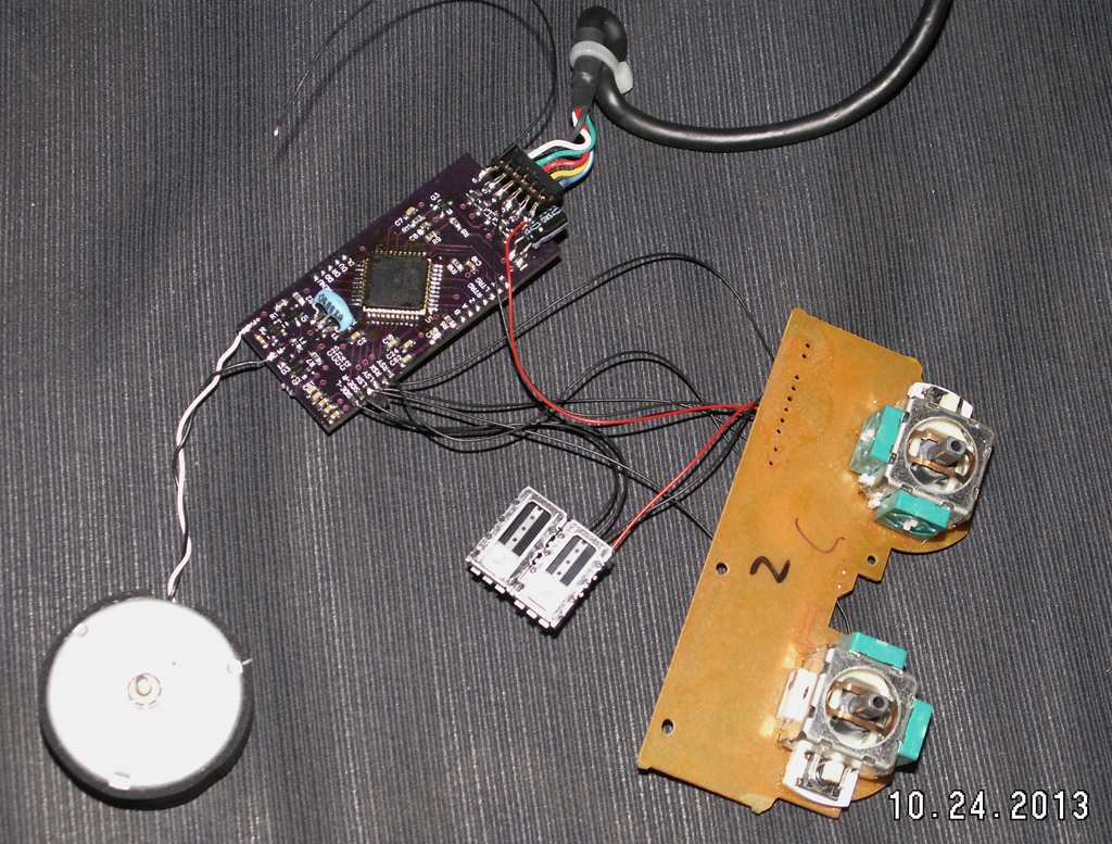
Everything works like it's supposed to. The PCB is 25mm x 50mm, so it's not quite as small as the miniDS2, but not a heck of a lot bigger either. All of the parts were kept on one side so the PCB also.
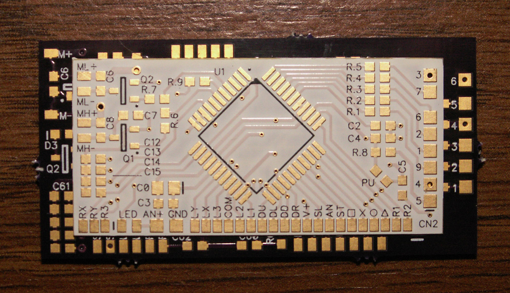
3D render of the final PCB for the miniGC with the decoupling caps and Analog power spots added.
Re: minGC Controller Board
Posted: Fri Oct 25, 2013 1:01 am
by emu_kidid
very nice, will you be selling these or providing the files for people to make their own?
I'm interested in one

Re: minGC Controller Board
Posted: Fri Oct 25, 2013 1:06 am
by APE992
I'll take 5.
Re: minGC Controller Board
Posted: Fri Oct 25, 2013 3:12 am
by |RDC|
Take 5 full boards, with everything installed and tested? or 5 'blank' boards, that are ready to have all of the part swapping done by you there? Because those will be 2 very different price tags.
The blank board would have C1 and Y1 pre-installed, and that's all. So in the case of the older wired GC controllers, that fatty thru hole Resonator and Capacitor wouldn't need to be swapped over, but that is all. Every other part from the wired GC controller would need to be swapped over by the user.
Likewise, a full board would have everything swapped over and tested here before it left.
If there's enough interest I'll get a batch of the PBCs made up, but anyone wanting a fully made board should be aware that it will cost more than what some used wired GC controller does, as I'm a human pick-n-place machine, not a mechanical one
so there's a little bit of work and time that goes into making up and testing a full board versus a blank board, where all I have to do is install 2 components.
Re: minGC Controller Board
Posted: Fri Oct 25, 2013 3:29 am
by emu_kidid
I would take 2 blank boards.
Re: minGC Controller Board
Posted: Fri Oct 25, 2013 7:37 am
by Duhasst0
i too would like 2 blank boards.
Re: minGC Controller Board
Posted: Fri Oct 25, 2013 9:34 am
by Benni
What is it good for?
Re: minGC Controller Board
Posted: Fri Oct 25, 2013 11:33 am
by emu_kidid
Re: minGC Controller Board
Posted: Fri Oct 25, 2013 2:28 pm
by |RDC|
Thanks to all that are showing interest in this. I'm looking into PCB and part pricing at a couple of places now and seeing where that is all going to land, as long as no one is in any kind of hurry here?
Right now the blank board (only C1 and Y1 are installed) is looking to be around $12.50 US or $15 International each, and that includes shipping also.
Making up a full board has a few ways that could go, but it's basically the cost of the blank board, plus the cost of the controller, plus the cost of labor. That's going to vary based on what a controller could be picked up for at the time, or if one was sent to be used. Then how much of the part swapping really needed to be done here. Someone might be comfortable with swapping over the Caps, Resistors and other smaller parts, but not want to touch the MCU.
Benni wrote:What is it good for?
That really depends on who it using it.
It's mostly an alternative to hacking down the actual controller PCB to make it smaller for a portable build. Where in most cases then the wiring has to be done on the MCU leads or some exposed traces, whereas this board has small pads for all of that soldering to be done.
It could also be stuffed into some other controller shell so you had an actual GC controller that was really some other controller without using some adapter, if it even existed. I've done that with the 360 and PS3 controllers, where a lot of PCB cutting and wiring up to small traces and vias has to be done.
It's more difficult to swap over the parts from the existing controller board to this board, or more expensive to have done, versus just taking a Dremel to the thing and cutting it up to make it smaller, but the end result is overall smaller, the complete controller and then easier to work with.
Re: minGC Controller Board
Posted: Fri Oct 25, 2013 5:18 pm
by megalomaniac
ill take 1 blank..
Re: minGC Controller Board
Posted: Sat Oct 26, 2013 7:09 am
by Benni
AH O.K.
for GCP´s...
Thank you.
Re: minGC Controller Board
Posted: Mon Oct 28, 2013 5:24 am
by |RDC|
Ordered up 20 of the PCBs to be made, and the parts for 10 blank boards are on order as well. Probably take around a month or so for the PCBs to show up here, parts much sooner, and I'll post back with updates when I start getting things here.
Re: minGC Controller Board
Posted: Mon Oct 28, 2013 6:09 am
by megalomaniac
sounds good
Re: minGC Controller Board
Posted: Thu Oct 31, 2013 2:08 am
by |RDC|
The components are here for the 10 blank boards.
The PCBs have also been made up now and are at the fab house. Now it's just a 7-30 day waiting game on shipping for them to get here so I can look them over, and if they're good, then I'll start building some blank ones up for you all that are still interested.
Re: minGC Controller Board
Posted: Thu Oct 31, 2013 3:15 am
by emu_kidid
Excellent, looking forward to 2.
Re: minGC Controller Board
Posted: Thu Oct 31, 2013 8:53 am
by doodisntbot
dood, where did you get tut idea? do nintendo staff teachin you somehow?
:)dood
Re: minGC Controller Board
Posted: Thu Oct 31, 2013 10:59 am
by |RDC|
Making a PCB smaller isn't really an idea, it's just making it smaller. I've done the
N64,
DualShock 2,
Wired CL and
Wireless CG2 controllers as well.
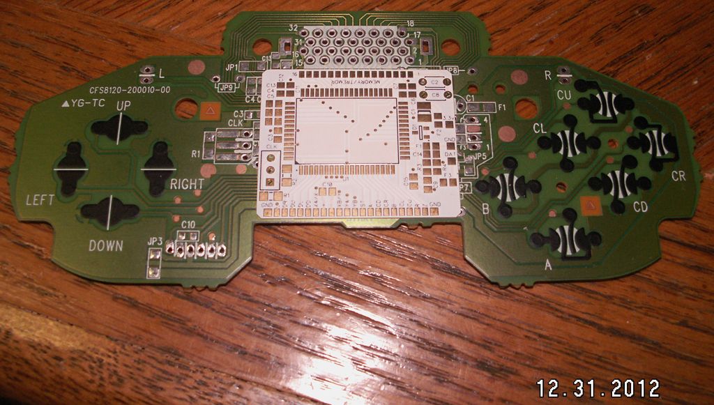
Nintendo had nothing to do with any of this, aside from making the original controller. I took the controller apart,
removed all of the parts and traced out the original PCB to make a schematic for designing the smaller PCB.
Re: minGC Controller Board
Posted: Fri Nov 01, 2013 6:14 am
by Duhasst0
i am looking forward to this as well.
Re: minGC Controller Board
Posted: Mon Nov 11, 2013 7:59 pm
by public-pervert
Just an idea: Why not add a spot for a SMD resistor on the L & R trigger? It would eliminate the need to poke with a external resistor, if using the double tact switch method. If the buyer wants to use the original slider pots, just bridge these spots.

Re: minGC Controller Board
Posted: Mon Nov 11, 2013 8:54 pm
by |RDC|
Installing a Resistor inline like that wouldn't work right.
Since the Left Trigger and Right Trigger go Hi when pressed, if the Resistors were installed from the LT and RT lines to Ground, then
they could just be left in there all the time. Then wiring a Tact switch form LT to AN+ could be used for Digital, or a 10k POT if they wanted Analog.
The reason I didn't do anything like that initially is because I've no idea how someone might want to use it. The 360 controllers work the same way, only with 10k POTs
instead of 35k, but I also left those alone so they could be done however.
It's not really a big enough change to warrant a new run of PCBs, plus the added cost and time involved, but if you want to pay for the new run of PCBs and
wait another month for them to get here, I can surely make the change and get some made up that way.
Re: minGC Controller Board
Posted: Tue Nov 12, 2013 1:04 am
by public-pervert
The idea is exactly to turn them digital, for small portables that does't have enough space for analog triggers.
Surely I won't, but would be good to see something like that if a new batch ever exists
Re: minGC Controller Board
Posted: Tue Nov 12, 2013 1:15 am
by tueidj
I think you're looking at the wrong lines, LTRG and RTRG are already digital buttons. The sliders are presumably connected to SIDE-L and SIDE-R.
Re: minGC Controller Board
Posted: Tue Nov 12, 2013 5:26 am
by |RDC|
@ tueidj - Correct, SIDE-L and SIDE-R are the Analog lines that would need to be done, not LTRG and RTRG. I had 360 controllers on the brain there with the LT and RT lingo.
@ public-pervert - Now that I'm looking at this thing some more, if you're really wanting them Digital, you can just replace C21 and C24 with a 10k 0603 and there you go, or better still
solder them on top of them in parallel so they Caps stay in there. Then just wire up your Tacts to SIDE-L and AN+ for Left, then SIDE-R and AN+ for Right.
Correction for an Analog setup also. Anyone wanting to keep them Analog should not install a 10k at C21 and C24, as with the Resistors installed and a 10k POT then used, it
will never release all the way. If Analog Slides are needed just wire the POT to GND, SIDE-x, AN+ for them. If they work backwards, then swap the AN+ and GND lines on the
POT.
Re: minGC Controller Board
Posted: Tue Nov 12, 2013 10:42 am
by public-pervert
@tuidj: You're right, I've showed the idea on the wrong spots. I've just look at it really quickly.
And nice to hear it'll work!
Re: minGC Controller Board
Posted: Tue Nov 12, 2013 12:50 pm
by Diminuendo
I feel this might be a better fit for the triggers, if we are going for simplicity

I'm trying to link to Modretro, but it doesn't seem to like me.
One button, jobs done, could put contacts further up the line to bypass this circuit