My WODE Gamecube Original
Posted: Mon Apr 21, 2014 2:28 am
Hello members of GC-Forever Forums, in first place, my apologies for the large absence of our forum of my part. Many occupations in my life and as i no had a Wode or Wiikey Fusion to mod my Gamecube or Wii to testing and share knowledge with you people, i refrained of participate in the topics.
However, recently my sister traveled to Europe for vacations, particulary to Spain and France, and i had the oportunity of obtain any of these chips and finally modify mi precious GC. The chip purchased is a Wode Jukebox, in the ChipSpain Store, in Spain which still has stock of this chip for 49 EUR.
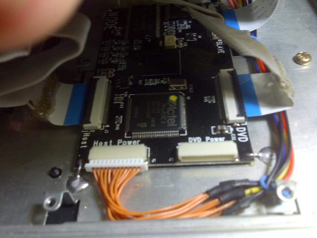
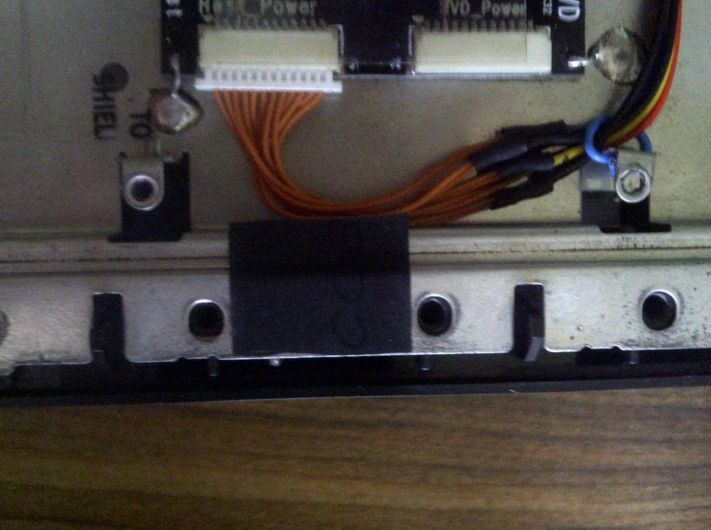
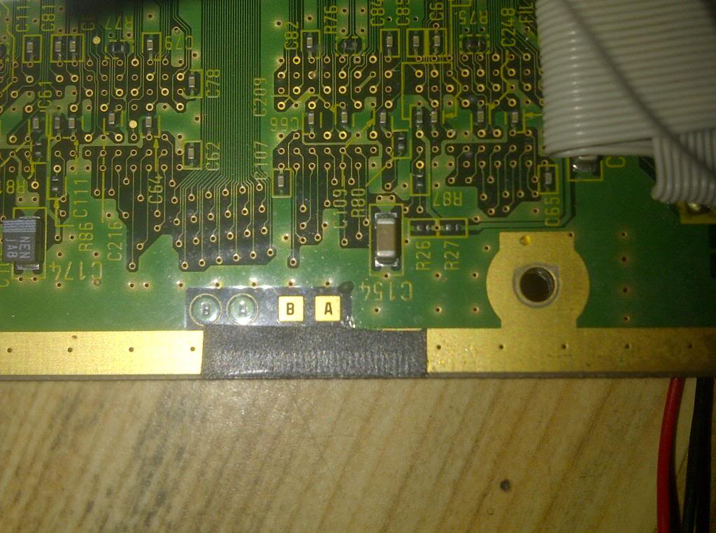
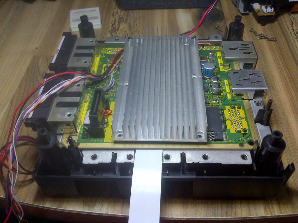
I modified my GameCube with Wode and i share my results with you. I used various tutorials of the GC-Forever forums to make the differents procedures and modify the cube. My intention was to preserve the GC integrity the most possible, for the use of original dvd drive to rip games and play the Streaming games, keeping the originality of gamecube. Due the big size of the Wode Jukebox, i decided the best place to locate the chip was under of the motherboard. To hold the chip, i soldered 3 wires to the metal cover to the isolated points in the corners and one more unwelded in the last corner of the wode chip. Also I made the connections for the power directly from the regulator board. Obviously i place the protective sticker under the Wode chip to insulate of the metal cover. (See The Picture below):
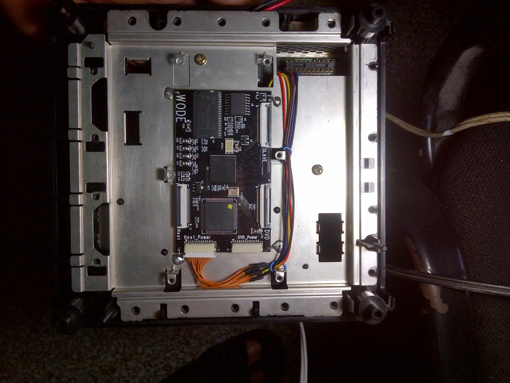
Once the chip set, I started making connections to connect the Wode with the motherboard and the DVD drive.
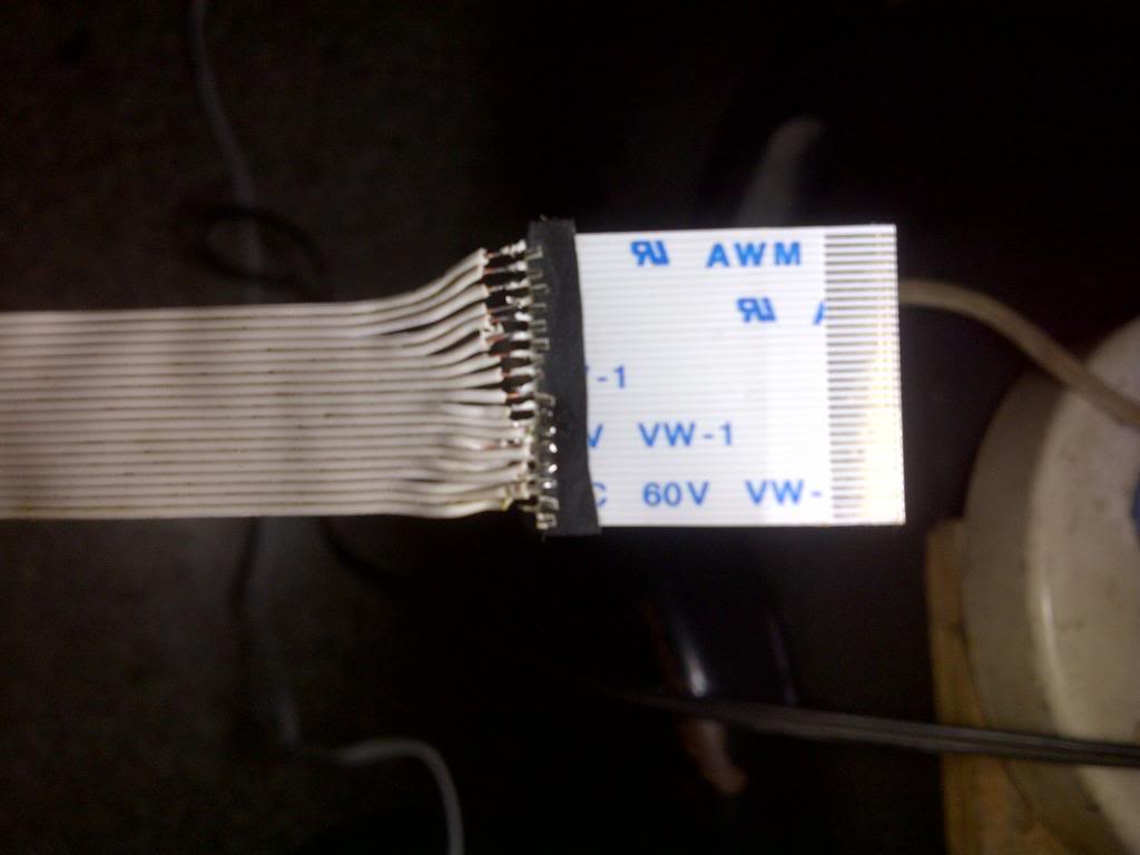
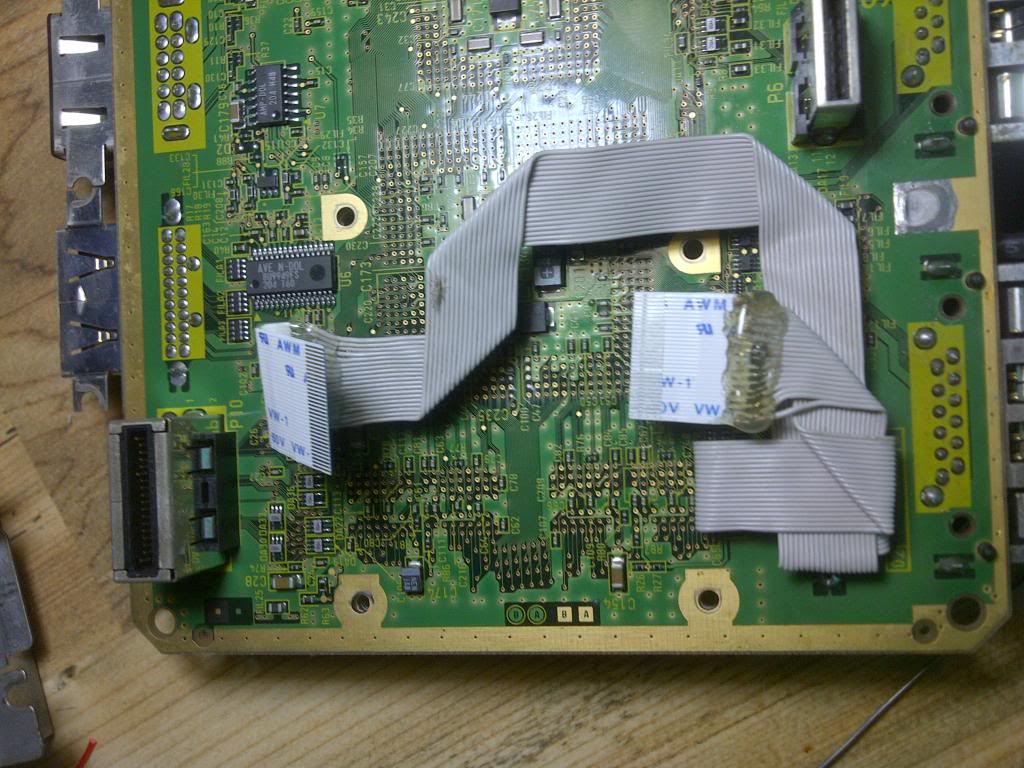
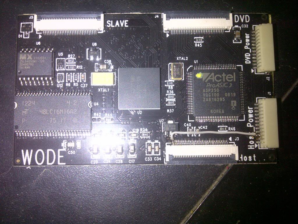
I based my work on this tutorial of Ashen: viewtopic.php?f=26&t=759 I did as it is explained there, only soldered 19 wires. I use 80 Wires IDE Cable:
Back side

Front Side.
I extracted the DVD drive connector from the mainboard, with no damage and with a dremel i made a little groove hole to pass the cable which connet again the dvd drive later.
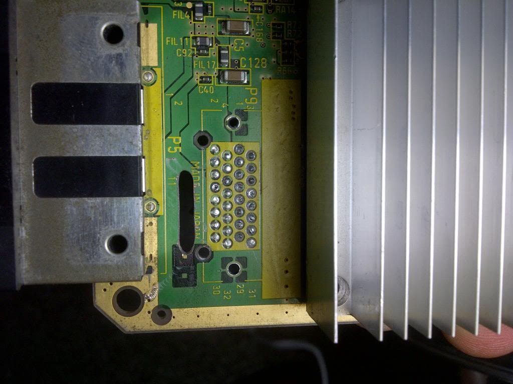
The Idea of extract the dvd drive connector with no damage, is recyclate later to connect the drive to wode maintaining the original shape.
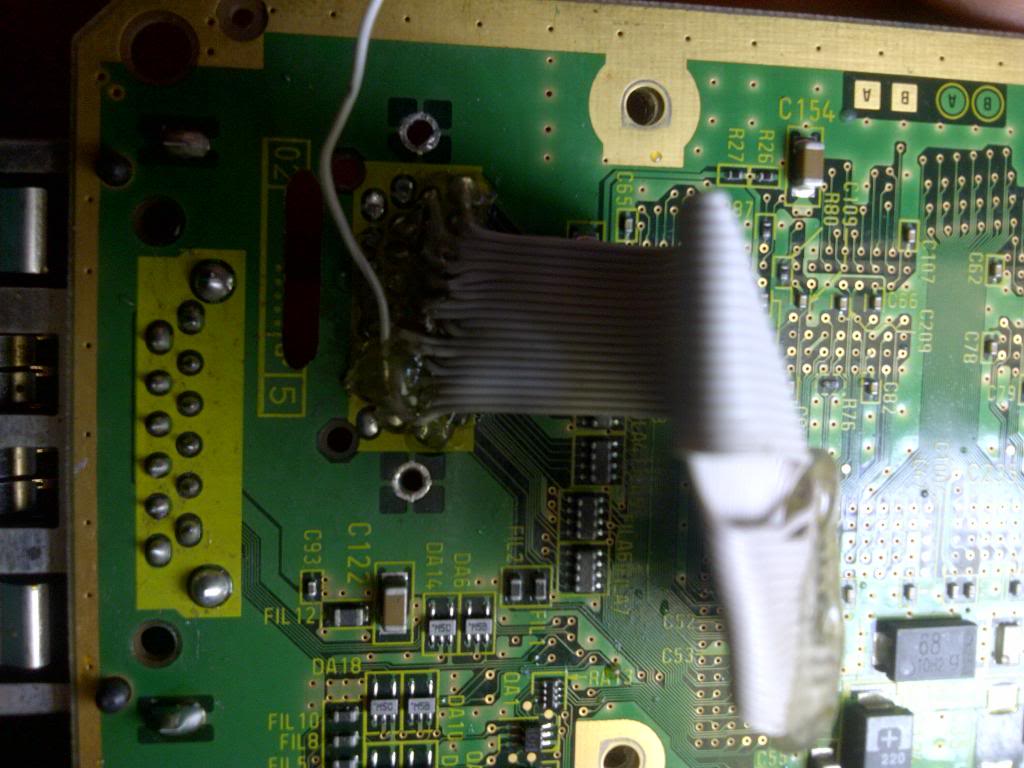
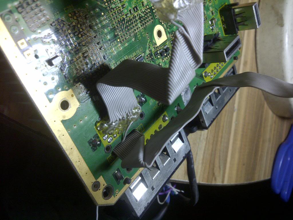
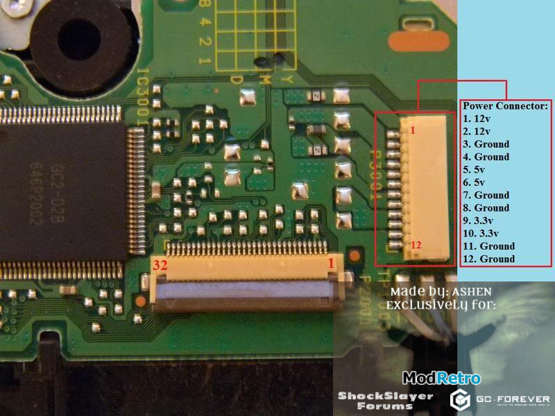
I soldered the cable going to the host connector of the wode to the motherboard of GC and covered it with hot glue to protec and isolate. I left the 29 pin cable to connect it apart later. To pins numeratiion i use this guide from Ashen: viewtopic.php?f=26&t=416
Later, I measured the distance needed to connect the cable to the host port of the wode, and I bent the wire to make it accurate and well accommodated.
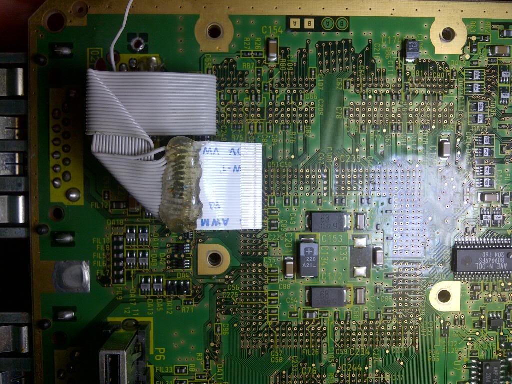
Then I started working in the cable connecting the DVD. I left it much longer due to the distance to the connector wode. Other measurements allowed me to bend the wire to make it well off, like the other, and pass right through the middle of the chip headspace.
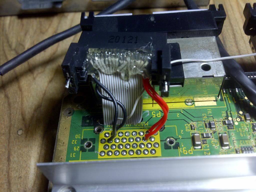
I pass the wire for the groove hole and commencing soldering every wire to the original dvd connector. Note: I cut each connector pin leaving only the distance needed for welding. For the pins numeration i use this guide from kel01: viewtopic.php?f=26&t=758&start=24
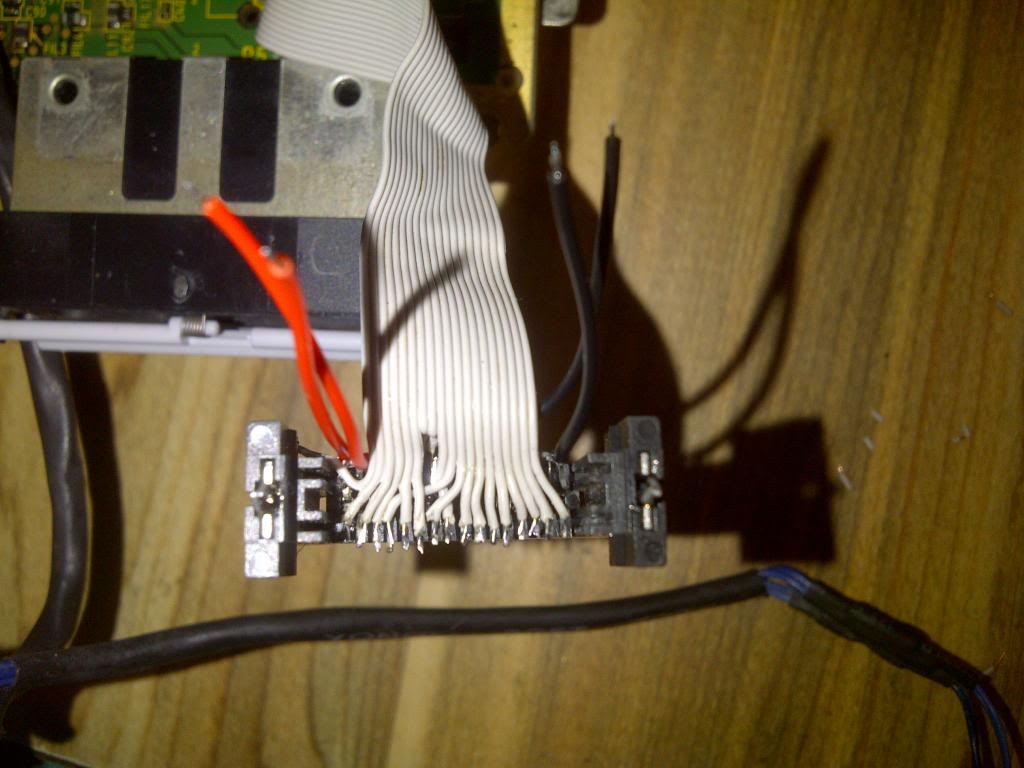
Also soldered the GND and 5V wires at their original points (only 2 each) and made welding, covered with hot glue. Note: The large alone white ide wire, is the pin 29 cable wode host side. The short alone wire, back the 5v wires (red) is the pin 29 cable DVD side.
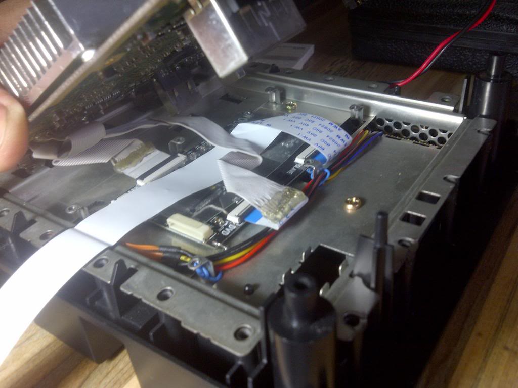
Locating the connector in place and welding the two attachment points.
Then order the cables correctly.
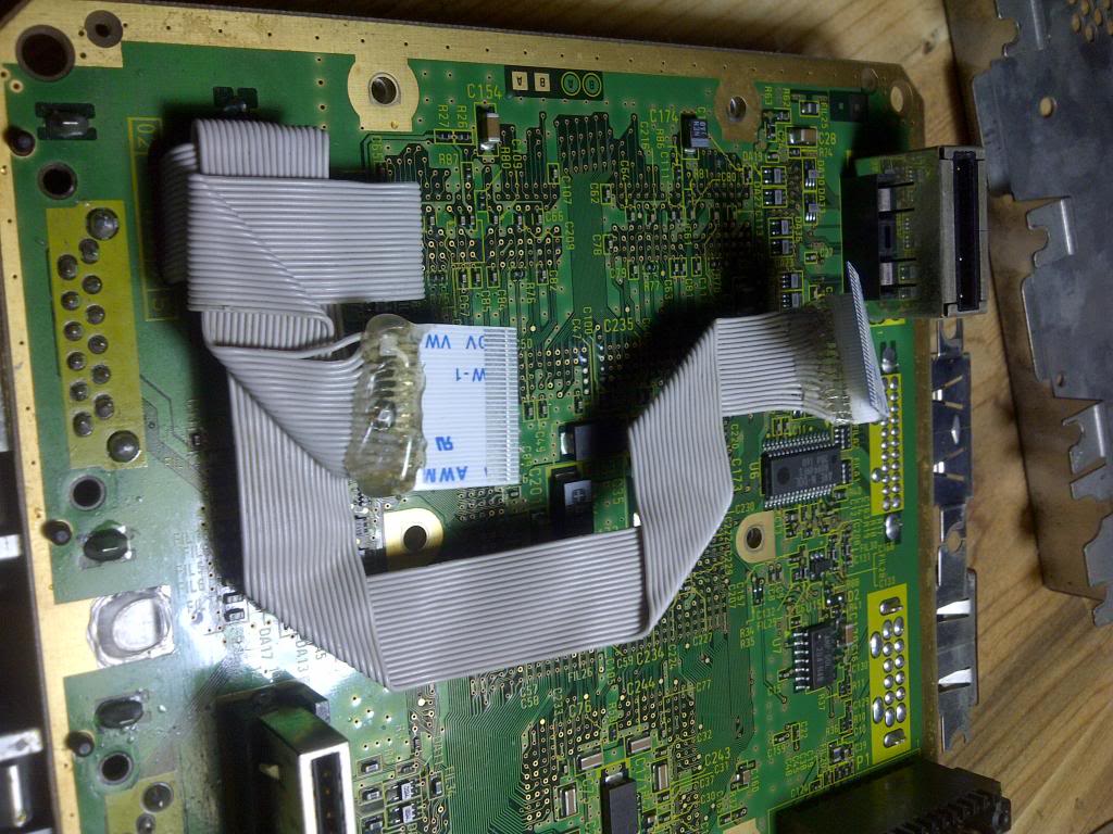
And connect ...
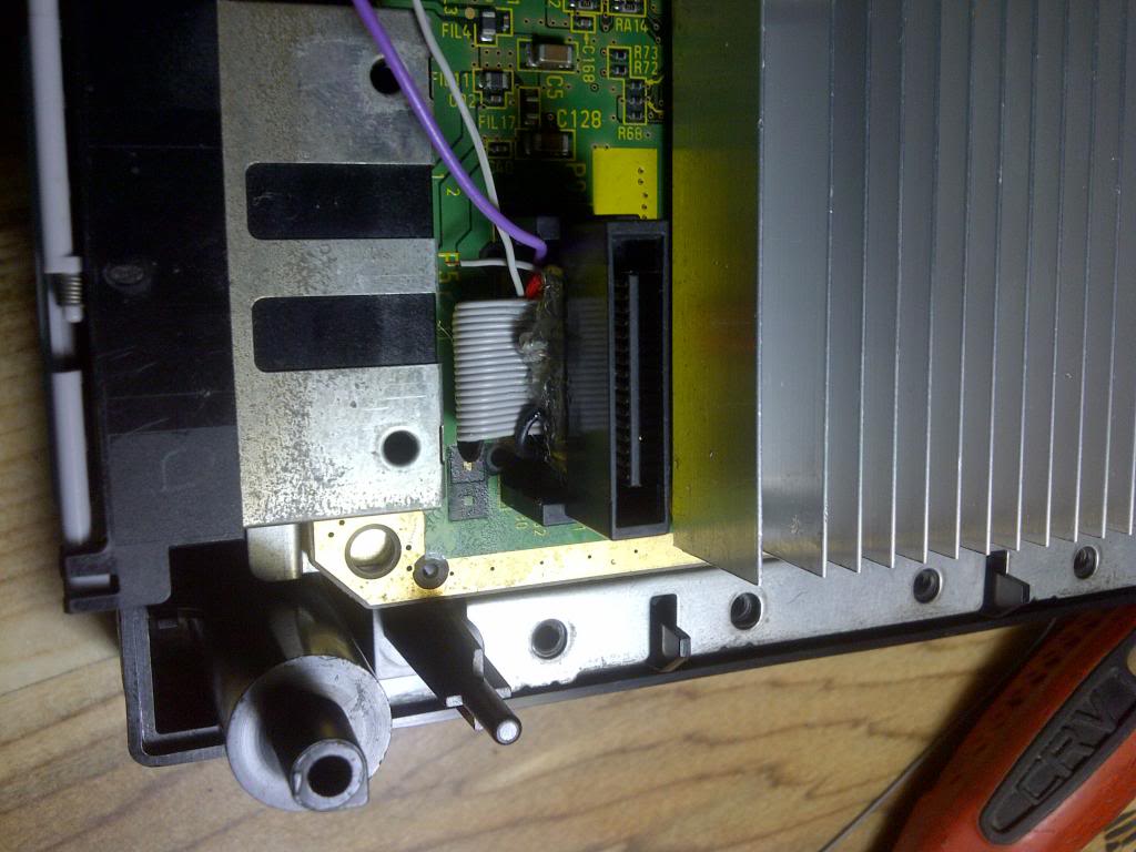
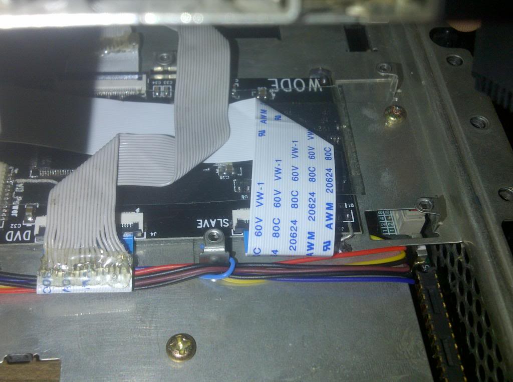
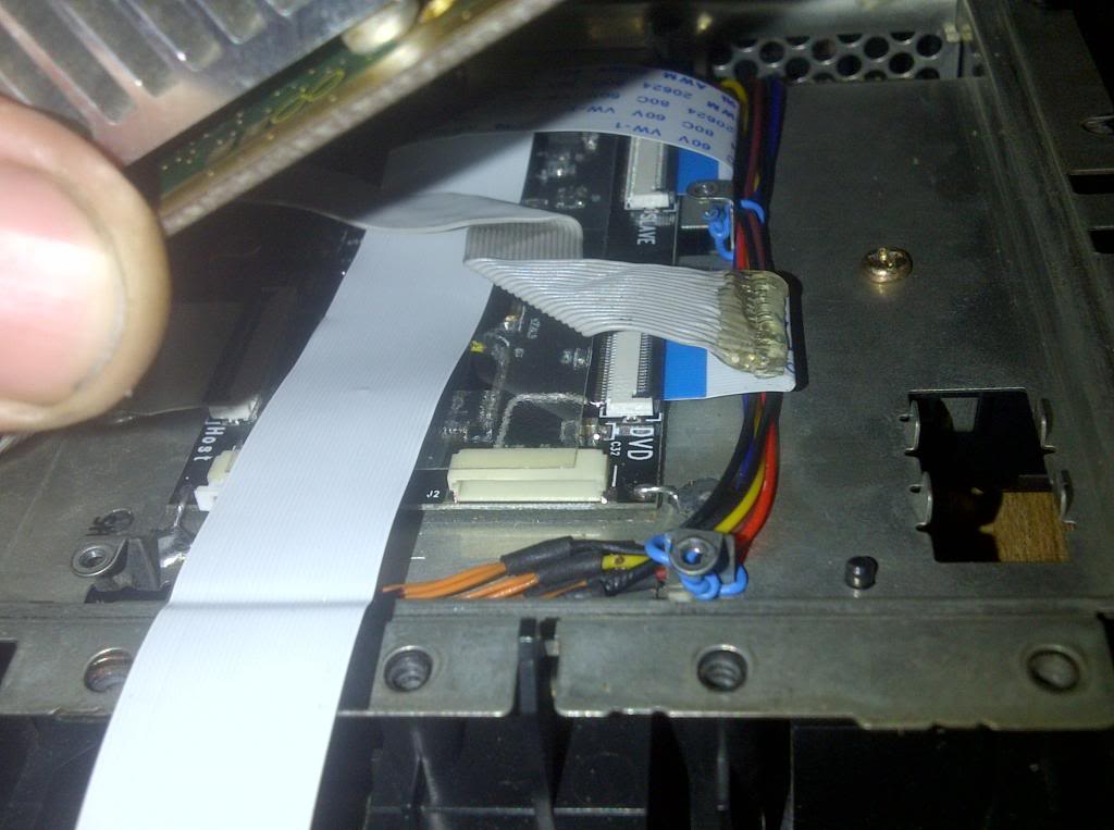
The site less problematic to place the flex of Wode Slave is passing through these 2 screws. I put on piece of electrical tape to protect the flex pressure between the mainboard and the metal cover.
Later connect the slave flex, bending so you pass under the dvd cable aligns with the site between the 2 screws where going out.
Put the mainboard in place.
Under construction.
Troubleshooting
At first, the wode on but did not work, and the error screen appeared in the GC. After thoroughly reviewing the connections and i make sure all was well, I noticed that the problem was in the switch that detects whether the lid is open or closed (Host connector-mainboard pin 23). In his tutorial, Ashen indicates, which this pin must be connected normally to GND through a normally closed push button or switch on / off. However, in this state, (pin 23 to gnd) the GC did not recognize the WODE and throws the error screen. The solution was to leave this switch off (pin 23 and gnd disconnected). I do not know if this is an isolated case, or if so, it sought answers reading a lot on forums and everywhere appears that this switch must be on. I would discuss this matter with you people if possible.
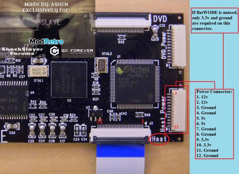
After, During performance testing, I noticed that the wode worked intermittently, ie sometimes not work and gamecube put the error screen, and others moments works correctly and runs backups for any mass storage. Reading and reading our forums for hours, in the tutorial of Ashen, i see the 32 pin 3.3v supply in the Wode Host Connector lacking. To fix this, i made a bridge between 3.3v of Wode power Host connector and pin 32 of the host connector. And put the upper protection sticker of wode.
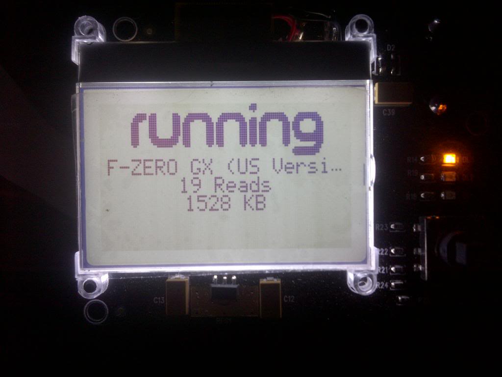
After this, the wode worked properly, at least from the storage devices. Maybe some random errors occasionally.
Also at the principle, my GC drive doesn't work. This problem occurred because i placed all the wires on dvd port incorrectly, specifically in inverted number position (1 in 29, 3 in 28, 4 in 27, etc) This error arises from the fact that the numbering of all wires and was not directly stated in the tutorials (at least i not see it).
I noticed the problem when I put a Wii drive unit to test, because the position of the flex that connects with the drive to the wode. and seeing the pin numbering of the wii units defined by Ashen.
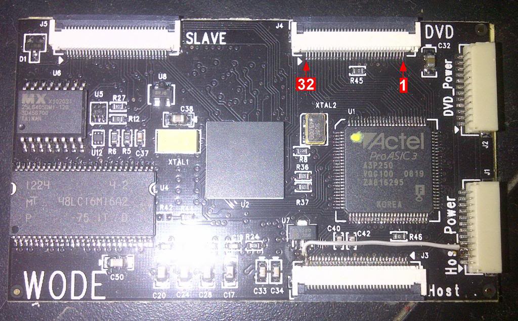
I builded every cable exactly to the Ashen tutorial, following the same numeration he is indicates to the host port. I thought it was the same for both cables. A fool error on mi part. Therefore remember that pin 1 is the one next to "DVD" word in WODE and32 is next to J4 as indicate megalomaniac in the discussion.
Under construction.
Sorry the bad english. Those English speakers who wish to correct paragraphs, write the private and gladly will place the relevant corrections.
However, recently my sister traveled to Europe for vacations, particulary to Spain and France, and i had the oportunity of obtain any of these chips and finally modify mi precious GC. The chip purchased is a Wode Jukebox, in the ChipSpain Store, in Spain which still has stock of this chip for 49 EUR.
I modified my GameCube with Wode and i share my results with you. I used various tutorials of the GC-Forever forums to make the differents procedures and modify the cube. My intention was to preserve the GC integrity the most possible, for the use of original dvd drive to rip games and play the Streaming games, keeping the originality of gamecube. Due the big size of the Wode Jukebox, i decided the best place to locate the chip was under of the motherboard. To hold the chip, i soldered 3 wires to the metal cover to the isolated points in the corners and one more unwelded in the last corner of the wode chip. Also I made the connections for the power directly from the regulator board. Obviously i place the protective sticker under the Wode chip to insulate of the metal cover. (See The Picture below):
Once the chip set, I started making connections to connect the Wode with the motherboard and the DVD drive.
I based my work on this tutorial of Ashen: viewtopic.php?f=26&t=759 I did as it is explained there, only soldered 19 wires. I use 80 Wires IDE Cable:
Back side
Front Side.
I extracted the DVD drive connector from the mainboard, with no damage and with a dremel i made a little groove hole to pass the cable which connet again the dvd drive later.
The Idea of extract the dvd drive connector with no damage, is recyclate later to connect the drive to wode maintaining the original shape.
I soldered the cable going to the host connector of the wode to the motherboard of GC and covered it with hot glue to protec and isolate. I left the 29 pin cable to connect it apart later. To pins numeratiion i use this guide from Ashen: viewtopic.php?f=26&t=416
Later, I measured the distance needed to connect the cable to the host port of the wode, and I bent the wire to make it accurate and well accommodated.
Then I started working in the cable connecting the DVD. I left it much longer due to the distance to the connector wode. Other measurements allowed me to bend the wire to make it well off, like the other, and pass right through the middle of the chip headspace.
I pass the wire for the groove hole and commencing soldering every wire to the original dvd connector. Note: I cut each connector pin leaving only the distance needed for welding. For the pins numeration i use this guide from kel01: viewtopic.php?f=26&t=758&start=24
Also soldered the GND and 5V wires at their original points (only 2 each) and made welding, covered with hot glue. Note: The large alone white ide wire, is the pin 29 cable wode host side. The short alone wire, back the 5v wires (red) is the pin 29 cable DVD side.
Locating the connector in place and welding the two attachment points.
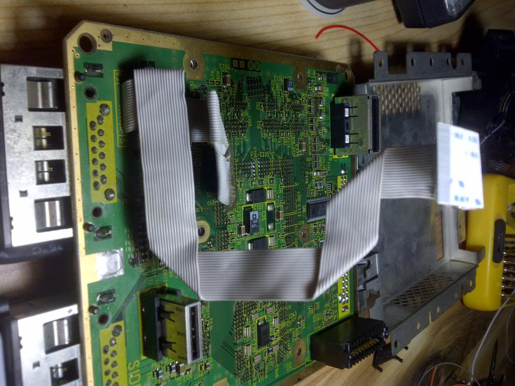
Then order the cables correctly.
And connect ...
The site less problematic to place the flex of Wode Slave is passing through these 2 screws. I put on piece of electrical tape to protect the flex pressure between the mainboard and the metal cover.
Later connect the slave flex, bending so you pass under the dvd cable aligns with the site between the 2 screws where going out.
Put the mainboard in place.
Under construction.
Troubleshooting
At first, the wode on but did not work, and the error screen appeared in the GC. After thoroughly reviewing the connections and i make sure all was well, I noticed that the problem was in the switch that detects whether the lid is open or closed (Host connector-mainboard pin 23). In his tutorial, Ashen indicates, which this pin must be connected normally to GND through a normally closed push button or switch on / off. However, in this state, (pin 23 to gnd) the GC did not recognize the WODE and throws the error screen. The solution was to leave this switch off (pin 23 and gnd disconnected). I do not know if this is an isolated case, or if so, it sought answers reading a lot on forums and everywhere appears that this switch must be on. I would discuss this matter with you people if possible.
After, During performance testing, I noticed that the wode worked intermittently, ie sometimes not work and gamecube put the error screen, and others moments works correctly and runs backups for any mass storage. Reading and reading our forums for hours, in the tutorial of Ashen, i see the 32 pin 3.3v supply in the Wode Host Connector lacking. To fix this, i made a bridge between 3.3v of Wode power Host connector and pin 32 of the host connector. And put the upper protection sticker of wode.
After this, the wode worked properly, at least from the storage devices. Maybe some random errors occasionally.
Also at the principle, my GC drive doesn't work. This problem occurred because i placed all the wires on dvd port incorrectly, specifically in inverted number position (1 in 29, 3 in 28, 4 in 27, etc) This error arises from the fact that the numbering of all wires and was not directly stated in the tutorials (at least i not see it).
I noticed the problem when I put a Wii drive unit to test, because the position of the flex that connects with the drive to the wode. and seeing the pin numbering of the wii units defined by Ashen.
I builded every cable exactly to the Ashen tutorial, following the same numeration he is indicates to the host port. I thought it was the same for both cables. A fool error on mi part. Therefore remember that pin 1 is the one next to "DVD" word in WODE and32 is next to J4 as indicate megalomaniac in the discussion.
Under construction.
Sorry the bad english. Those English speakers who wish to correct paragraphs, write the private and gladly will place the relevant corrections.