Cloning the GameCube component cable

Portables, case replacements, mods etc, all in here!
User avatar
Unseen
Posts: 190
Joined: Fri Jul 04, 2014 11:52 am

Re: Cloning the GameCube component cable

Post by Unseen » Mon Nov 30, 2015 6:40 pm

Xaranar wrote:Just upgraded to the new version, and I can confirm that the wobbling issue has been resolved, thanks!
Yay!

(someone else reported that 2.1 now causes issues with a certain Dell monitor that was ok before =( )
Asking for support by PM is anti-social. Ask in an open forum instead, so other people can benefit from the answers!
Xaranar
Posts: 109
Joined: Tue Sep 22, 2015 12:50 pm

Re: Cloning the GameCube component cable

Post by Xaranar » Mon Nov 30, 2015 8:46 pm

Unseen wrote: Yay!

(someone else reported that 2.1 now causes issues with a certain Dell monitor that was ok before =( )
Urgh, fix one thing and something else breaks! Oh dear, well, I appreciate all your hard work on this. When I put the new software on my Pluto II I totally didn't know that you didn't need the external power supply in order to flash it, so I plugged my 9V DC adapter into my little TXDI board, and when I plugged that into my Pluto, to my surprise, my Cube powered on! Well, the LED and the fan did, though I don't know if it was outputting a display signal as it wasn't plugged in to my monitor. Anyway, flashing the board that way didn't seem to work, so I plugged the GC power supply in and switched it on, and was able to flash the board that way. Thanks for the free settings reset, by the way :P
meneerbeer
Posts: 212
Joined: Wed Sep 03, 2014 9:13 am

Re: Cloning the GameCube component cable

Post by meneerbeer » Tue Dec 01, 2015 11:00 am

I have been thinking about making it possible to upgrade the firmware using GC homebrew. Basically we need means for the GC to communicate data to the FPGA, so it is able to write the new firmware to the flash memory.

I guess this could be done through the controller line? Make a homebrew that detects when controller 1 is unplugged and then send a special command + the data we want to write to the flash, for instance. I guess it would be slow. Furthermore, communicating back through the controller line has not been implemented yet, so checking if the flash went alright, etc. will take more work.

Perhaps we can use a different bus for this. Would it be possible for instance to add the board as an EXI device to the GameCube? Decoding the EXI bus with the FPGA seems rather straightforward and should not take that many resources, so perhaps it will still fit.
User avatar
Unseen
Posts: 190
Joined: Fri Jul 04, 2014 11:52 am

Re: Cloning the GameCube component cable

Post by Unseen » Tue Dec 01, 2015 11:21 am

meneerbeer wrote:I guess this could be done through the controller line?
I would just re-use the existing high-bandwidth channel from the Gamecube to the FPGA: The video data stream. It has a few limitations because it can't output all possible 8-bit-values, but even with just a single line on screen and four bit per pixel you can transmit about 20 kByte/s (60fps, 640 pixels, no delays). To acknowledge a successful data reception, the FPGA could use the Cable Detect pin.

The more interesting question is how to implement it in a way that is brick-proof. The Spartan 3A uses a CRC check to verify the validity of the bitstream and has some features to allow for main+fallback bitstreams in the same SPI flash, but IIRC there were some details that need to be taken care of.

The main reason why GCVideo doesn't have a firmware update system already is my lazyness: I hoped that I wouldn't need to release any further versions, so why implement something that wouldn't be used anyway? =)
Asking for support by PM is anti-social. Ask in an open forum instead, so other people can benefit from the answers!
meneerbeer
Posts: 212
Joined: Wed Sep 03, 2014 9:13 am

Re: Cloning the GameCube component cable

Post by meneerbeer » Tue Dec 01, 2015 11:53 am

I had been thinking about that as well. How can we distinguish between video and firmware data though?
User avatar
Unseen
Posts: 190
Joined: Fri Jul 04, 2014 11:52 am

Re: Cloning the GameCube component cable

Post by Unseen » Tue Dec 01, 2015 12:00 pm

meneerbeer wrote:I had been thinking about that as well. How can we distinguish between video and firmware data though?
I would probably ask the user to select an "Update firmware" option in the OSD and add some checksum to the data to be on the safe side.
Asking for support by PM is anti-social. Ask in an open forum instead, so other people can benefit from the answers!
User avatar
bentomo
Posts: 51
Joined: Sun Jun 05, 2011 6:39 pm

Re: Cloning the GameCube component cable

Post by bentomo » Tue Dec 29, 2015 6:59 pm

Ok so I have a question.

Do you think it would be possible to convert the digital signal from the gamecube directly to an 18bpp or 24bpp clocked 40 pin bus that could drive a stand alone TFT LCD display?

I've been looking at using a shuriken video to go to HDMI and using a TI TFP401 to go from HDMI to the pixel bus, but I feel like the middle man, HDMI, could be eliminated with a beefier FPGA.

Do you guys think this is feasible?

My intention is portables of course.
ImageImageImageImageImageImage
User avatar
Unseen
Posts: 190
Joined: Fri Jul 04, 2014 11:52 am

Re: Cloning the GameCube component cable

Post by Unseen » Tue Dec 29, 2015 8:37 pm

bentomo wrote:Do you think it would be possible to convert the digital signal from the gamecube directly to an 18bpp or 24bpp clocked 40 pin bus that could drive a stand alone TFT LCD display?
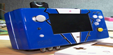
Probably yes, if the timing required by the TFT is close enough to standard EDTV that it can be fed with the Cube pixel data without adding a full frame buffer. I don't have any experience with driving stand-alone TFTs though, so this is pure guesswork.
Asking for support by PM is anti-social. Ask in an open forum instead, so other people can benefit from the answers!
User avatar
bentomo
Posts: 51
Joined: Sun Jun 05, 2011 6:39 pm

Re: Cloning the GameCube component cable

Post by bentomo » Tue Dec 29, 2015 11:06 pm

It seems to be very similar to the way that you go from the machX02 to the DAC on the GCVideo lite. A lot of application specific lcd controllers simply use the 24bits of color and control those pins along with a hsync, vsync, and clock to control each pixel.

Of course this means that you would have to use a specific lcd model for your timings, but timings can always be changed in the code. If the X02 can use about 30 of it's I/O pins to "print" the color to an lcd at an appropriate time then there would be no need for a large video frame buffer.

At least that's what I've been taking from my research.

I'm going more in depth with the VHDL and seeing how much I would have to change to do something like this. It should work in theory.
ImageImageImageImageImageImage
pyroholic
Posts: 58
Joined: Tue Nov 25, 2014 8:22 am

Re: Cloning the GameCube component cable

Post by pyroholic » Tue Jan 12, 2016 9:17 pm

It should be possible without a full frame buffer. unless the number of blanking lines differ greatly there should be no need to buffer much data. Most LCD-displays I have worked with have a configurable number of blanking lines and number of pixels/line, if you find a clock frequency so that frame timing is equal you're good to go. Some displays can tolerate cheating so that you can skip a couple of pixels on the last blanking line etc. to simplify finding a suitable clock. You should have the same relation between the clocks that you have between source and output video.
Rezirex
Posts: 2
Joined: Sun Jun 07, 2015 6:45 pm

Re: Cloning the GameCube component cable

Post by Rezirex » Sat Jan 23, 2016 4:14 am

I currently own a J-R Programmer found here.
Is there any reason this wouldn't be a working substitute to a Lattice programmer? I'd hate to buy one if I already own an alternative.
meneerbeer
Posts: 212
Joined: Wed Sep 03, 2014 9:13 am

Re: Cloning the GameCube component cable

Post by meneerbeer » Sat Jan 23, 2016 9:23 am

You could check if you can use the .svf file with your programmer.

Check the FAQ:
The .svf file is useful for programming the chip with non-Lattice tools which support SVF playback, e.g. Xilinx' Impact.
Ash1487
Posts: 3
Joined: Sun Jan 24, 2016 12:16 pm

Re: Cloning the GameCube component cable metal shield and plastic cover wanted

Post by Ash1487 » Mon Jan 25, 2016 12:27 am

Anyone have some metal shields and plastic covers left over from modding I require a couple to repair a component cable.

Thanks in advance

Ashley
Aurelio
Posts: 25
Joined: Fri Jun 05, 2015 8:53 am

Re: Cloning the GameCube component cable

Post by Aurelio » Fri Feb 19, 2016 12:30 pm

Hello, I've a problem with VGA output. I don't know why, but I see some odd vertical lines on the image. I'm displaying it on a Dalian Good Display 5.6" using 480p.
I've uploaded them here: http://imgur.com/a/BMs3I

Could it be related to some timing issues? I checked vsync and hsync pulses and I get durations of ~190 us and ~2.4 us (respectively), which are not standard. Is there a way to change their durations?
Thanks
User avatar
Unseen
Posts: 190
Joined: Fri Jul 04, 2014 11:52 am

Re: Cloning the GameCube component cable

Post by Unseen » Fri Feb 19, 2016 12:42 pm

Aurelio wrote:I checked vsync and hsync pulses and I get durations of ~190 us and ~2.4 us (respectively), which are not standard.
Are you sure about the 190 microseconds? IIRC the 480p output of the Gamecube was close to if not spot-on to the CEA timings, but 190 microseconds would be a VSync length of 7.125 lines instead of the expected 6 lines (160 microseconds).
Is there a way to change their durations?
No, the sync outputs are just the decoded signals provided by the Gamecube.
Asking for support by PM is anti-social. Ask in an open forum instead, so other people can benefit from the answers!
Aurelio
Posts: 25
Joined: Fri Jun 05, 2015 8:53 am

Re: Cloning the GameCube component cable

Post by Aurelio » Fri Feb 19, 2016 1:07 pm

Unseen wrote:
Aurelio wrote:I checked vsync and hsync pulses and I get durations of ~190 us and ~2.4 us (respectively), which are not standard.
Are you sure about the 190 microseconds? IIRC the 480p output of the Gamecube was close to if not spot-on to the CEA timings, but 190 microseconds would be a VSync length of 7.125 lines instead of the expected 6 lines (160 microseconds).
Is there a way to change their durations?
No, the sync outputs are just the decoded signals provided by the Gamecube.
Thank you for answering me.
When I turn on the GameCube the vsync duration is 160 us and it stays this way until I run a game from swiss when it changes to 190 us (still the lines are visible also in swiss).
About changing the sync durations I was thinking about two counters that could be reset on the falling edge of the sync flags to provide correct timing on output syncs. Could it be possible?

EDIT: I'm using a PAL console, could the problem be related to this? Still I get the same lines both with NTSC and PAL games
User avatar
Unseen
Posts: 190
Joined: Fri Jul 04, 2014 11:52 am

Re: Cloning the GameCube component cable

Post by Unseen » Fri Feb 19, 2016 1:24 pm

Aurelio wrote:When I turn on the GameCube the vsync duration is 160 us and it stays this way until I run a game from swiss when it changes to 190 us (still the lines are visible also in swiss).
The last part of that sentence seems to indicate to me that the lines show up in swiss even though the sync length is still 160us? In that case I'm not sure if changing the timing would help.
About changing the sync durations I was thinking about two counters that could be reset on the falling edge of the sync flags to provide correct timing on output syncs. Could it be possible?
In theory yes, in practice I wonder if it would introduce new compatibility issues - it's not just about the sync duration, the position is also important.
EDIT: I'm using a PAL console, could the problem be related to this? Still I get the same lines both with NTSC and PAL games
I'm a PAL user too and I haven't seen such stripes yet. NTSC or PAL isn't that much of a difference for the Gamecube anway since it uses a 13.5/27MHz pixel clock, which is the the same pixel clock used for standard 480i/576i/480p/576p video timings.
Asking for support by PM is anti-social. Ask in an open forum instead, so other people can benefit from the answers!
Aurelio
Posts: 25
Joined: Fri Jun 05, 2015 8:53 am

Re: Cloning the GameCube component cable

Post by Aurelio » Fri Feb 19, 2016 2:02 pm

Thank you a lot. I've connected the gcvideo Lite to my TV and I have the same issue. I guess that it could be some wiring issue. I will rewire everything and test it again.
bobrocks95
Posts: 161
Joined: Fri Jul 26, 2013 11:19 pm

Re: Cloning the GameCube component cable

Post by bobrocks95 » Fri Feb 19, 2016 2:58 pm

That could be a sign the clock line is too close to others, right?
Aurelio
Posts: 25
Joined: Fri Jun 05, 2015 8:53 am

Re: Cloning the GameCube component cable

Post by Aurelio » Fri Feb 19, 2016 6:13 pm

I've tried to rewire again everything using different wires, but nothing changed. I'm going to try to assemble a new gcvideo lite. Do you have any idea if it could be some particular component causing this issue?
Thanks
Mooper
Posts: 7
Joined: Tue May 05, 2015 5:50 pm

Re: Cloning the GameCube component cable

Post by Mooper » Fri Feb 19, 2016 6:37 pm

Aurelio, try using the auto adjust on your screen while in the swiss menu.

Check out this thread too
http://forums.modretro.com/viewtopic.php?f=36&t=10690

If that doesn't fix it, I had some problems with the voltage from the regulator going to the gpu being too low.
User avatar
Unseen
Posts: 190
Joined: Fri Jul 04, 2014 11:52 am

Re: Cloning the GameCube component cable

Post by Unseen » Fri Feb 19, 2016 6:52 pm

Aurelio wrote:I've tried to rewire again everything using different wires, but nothing changed. I'm going to try to assemble a new gcvideo lite. Do you have any idea if it could be some particular component causing this issue?
I can't think of any specific fault on a GCVideo Lite board that would cause this - my first idea was interference from the SPDIF signal, but that wouldn't be vertically aligned between adjacent image lines.
Asking for support by PM is anti-social. Ask in an open forum instead, so other people can benefit from the answers!
Aurelio
Posts: 25
Joined: Fri Jun 05, 2015 8:53 am

Re: Cloning the GameCube component cable

Post by Aurelio » Fri Feb 19, 2016 7:32 pm

Oh, now that you tell me, could it be the fact that I've not connected the three i2s signals? (since I don't need them)
EDIT: I've connected them, still no change...
Aurelio
Posts: 25
Joined: Fri Jun 05, 2015 8:53 am

Re: Cloning the GameCube component cable

Post by Aurelio » Sat Feb 20, 2016 12:02 pm

Sorry if I post again. I've a "theory" about my issue. Both my LCD and my TV don't seem to handle 480i, while they show 480p but with those lines. Is it possible that since they can't handle 480i a slight difference in the timings (front/back porch?) can cause those lines? Maybe a LCD capable of handling 480i is more flexible to timings differences and it can handle the video with no issues... could it be right?

Oh BTW, I think this might be useful to others. I found a way to flash the FPGA with a cheap Altera USB Blaster clone. This works also on non-Windows OS.
First of all I've installed urjtag, libftdi and libusb. Then I downloaded the BSDL file of the FPGA from here: http://www.latticesemi.com/Products/FPG ... chXO2.aspx
Then from the terminal I've run urjtag (the command name is just "jtag") and I executed these commands:
cable UsbBlaster
bsdl path /Users/Aurelio
detect
part 0
svf /Users/Aurelio/gcvideolite.svf
In the first command you have to specify the path to the directory where the BSDL of the FPGA is stored (/Users/Aurelio in my case), while in the last one you have to specify the complete path to the .svf file of gcvideolite.
I don't know if these informations were already posted by someone. If that's not the case I hope that someone could find them useful :)
Last edited by Aurelio on Tue Oct 18, 2016 9:21 pm, edited 1 time in total.
User avatar
Unseen
Posts: 190
Joined: Fri Jul 04, 2014 11:52 am

Re: Cloning the GameCube component cable

Post by Unseen » Sun Feb 21, 2016 2:37 pm

Aurelio wrote:Sorry if I post again. I've a "theory" about my issue. Both my LCD and my TV don't seem to handle 480i, while they show 480p but with those lines. Is it possible that since they can't handle 480i a slight difference in the timings (front/back porch?) can cause those lines? Maybe a LCD capable of handling 480i is more flexible to timings differences and it can handle the video with no issues... could it be right?
No, I don't think it is (directly) related to 480i support.

To test this, I connected a GCVideo Lite board to the VGA input of my TV (does not support 480i on that input) and to an old Sony TFT (PC-only, does not support interlaced at all) and ran the 240p test suite in 480p mode to display a solid, dark gray screen. On the TV, I did not see any vertical stripes at all, but on the Sony there were faint stripes visible. A closer examination of the video signal from the board using an oscilloscope revealed the cuplrit: There is a small interference from the 27MHz pixel clock on the three RGB lines. This does not matter if the display samples the video data with the same frequency because it is just a small, constant offset at each sample point. However, if the display incorrectly interprets the signal as 640x480 instead of 720x480, the phase of the sampling points and the 27MHz interference shifts with every pixel, resulting in vertical stripe artifacts.

Unfortunately, I don't see any option to fix this on the FPGA side - even if you were willing to live with a slightly reduced horizontal resolution, outputting 640x480 instead of 720x480 is not possible with the FPGA on this board because it has no PLL to generate the necessary pixel clock. A modified PCB layout might help, but I'm not familiar enough with low-noise analog circuit design to figure out what needs to be changed. One thing you could try is to solder three 120pF capacitors in parallel with the three 75 ohm resistors (R2/R3/R4) next to the RGB output pads - since the resistors are SMD, stacking a capacitor on top shouldn't be too hard. If this reduces the stripes, but does not eliminate them you could also try higher capacitor values, but the higher you go the more sharpness you'll lose.

Of course if my theory is correct, the best solution would still be a display that samples the signal with 720 pixels horizontally instead of 640.
Oh BTW, I think this might be useful to others. I found a way to flash the FPGA with a cheap Altera USB Blaster clone. This works also on non-Windows OS.
Neat, thanks!
Asking for support by PM is anti-social. Ask in an open forum instead, so other people can benefit from the answers!
Post Reply