Page 1 of 1
GC VIDEO Project P
Posted: Mon Mar 20, 2017 4:34 am
by zeldaxpro
Update: After much consideration with talking to other members, as well as many feedback and improvements I have received, I have decided to to take everyone's advice and improve the product before any kind of true beta release. Thank you.
Re: GC VIDEO PLUG N PLAY: IT'S FINALLY HERE!!
Posted: Mon Mar 20, 2017 6:08 am
by megalomaniac
i always wondered who was gonna be the first to try to release the PCB sandwich solution
...you know, a proper replacement connector would be much better in the long run
Re: GC VIDEO PLUG N PLAY: IT'S FINALLY HERE!!
Posted: Mon Mar 20, 2017 6:29 am
by Noah7
Re: GC VIDEO PLUG N PLAY: IT'S FINALLY HERE!!
Posted: Mon Mar 20, 2017 11:17 am
by JimmySummer
Great job!
Re: GC VIDEO PLUG N PLAY: IT'S FINALLY HERE!!
Posted: Mon Mar 20, 2017 11:20 am
by meneerbeer
megalomaniac wrote:i always wondered who was gonna be the first to try to release the PCB sandwich solution
...you know, a proper replacement connector would be much better in the long run
This.
Re: GC VIDEO PLUG N PLAY: IT'S FINALLY HERE!!
Posted: Mon Mar 20, 2017 2:17 pm
by zeldaxpro
I appreciate all the feedback and will take all your comments seriously. I think I've already addressed a lot of your concerns in the design, but I've edited the topic to reflect that this is a very small run of pre-production boards and that I'm open to any improvements and design changes. Thank you!
Re: GC VIDEO PLUG N PLAY: IT'S FINALLY HERE!!
Posted: Mon Mar 20, 2017 3:19 pm
by megalomaniac
here is some feedback to consider on how to re-evaluate to possibly come up with something better, a little more safer, and more secure.
the biggest problem with connector is the pins. there is no protection for them at all
in this quickly drawn pic you can see whats happening here in the official component plug:
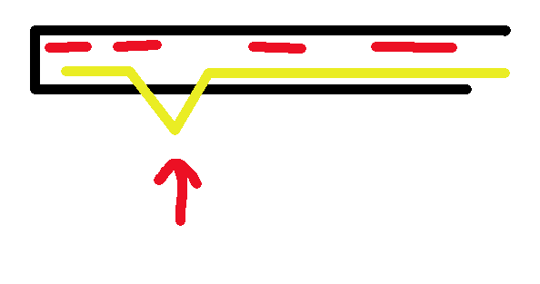
the pins on the official connector are able to move up into the connector housing which allows for a zero insertion force across the pins with the physical surround of the connector absorbing the insertion force and the weight of the circuitboard, housing, and cable.
Your pins do not have any protection against insertion force and the weight that will be applied across them once inserted. This will lead to malformed pins carrying the burden of the weight since there is nothing else there to offset the weight from the pins themselves.
Also the pins do not have any alignment guides to prevent them from straying left / right due to improper insertion (a curious 5yr old when you are not looking, or just an idiot adult for that matter.) once those pins stray from their original position they have potential to short without the user even realizing they might be misaligned and could fry the system.
Am i correct in assuming that these pins are also individually soldered directly onto the board one by one? The reason for this assumption is because i am not aware of any type of pins on the market that meet the nintendo proprietary spacing unless you are using a group of pins with spacing which is not exact proper spacing but possibly "
close enough to get er done".
I also assume you have not performed any testing to determine minimum number of mechanical connections before expected failure.
Its easy to make something that works for now but to make sure the connector still holds up 20yrs from now is a different story.
Re: GC VIDEO PLUG N PLAY: IT'S FINALLY HERE!!
Posted: Mon Mar 20, 2017 6:52 pm
by zeldaxpro
Thanks everyone for the additional advice and comments, I will be taking them in consideration. I have also edited the price to be re evaluated for the time being. Again, this is a pre-production run to see how things go. Thank you.