i love this thread and the idea behind it!
Gamecube component cable
Re: Gamecube component cable
hahaha those drawings are amazing 
i love this thread and the idea behind it!
i love this thread and the idea behind it!
please search before you ask - a lot has been discussed already!
(or use google with "site:gc-forever.com *term*")
http://is.gd/MDmZcr
we also have a wiki filled with knowledge
http://is.gd/dX58Rm
(or use google with "site:gc-forever.com *term*")
http://is.gd/MDmZcr
we also have a wiki filled with knowledge
http://is.gd/dX58Rm
-
megalomaniac

- Posts: 2480
- Joined: Sun Aug 21, 2011 5:33 am
- Location: Drunk in Texas
- Contact:
Re: Gamecube component cable
ok...
good news, the "non-working" gamecubes arrived...
bad news, they all work...
normally we want items to fully work or at least to the minimum standards where easy repair or portabilization can occur...
in this scenario, i wanted some d-e-a-d cubes to play with so i wouldnt feel bad about scrapping perfectly working cubes....
so this has led me to another idea
i can begin layouts, photo shoot, get feedback, then move forward.
in the process, i can make one of these cubes fully modified and ready for use for someone who may question their soldering skills or who may not already have a DOL-001.
maybe also add a homemade xeno with on board serial programmer (if interested)
since i was gonna sell one of these working cubes on ebay anyways(un-modified), might as well offer it here first (fully modified)
no further info about it at this time...its just an idea
main thing, the cubes arrived and i can move forward now...
>>> BadAssConsoles.com <<<emu_kidid wrote: beer is like WD40 for megalomaniac's brain, gets the gears moving
Re: Gamecube component cable
hmmm fully modded with diy-xeno sounds cool - i guess i'd buy it. well the mainboard only of course!
....but on the other hand, i have a lot of cubes, so if somebody else wants it i guess i'd pass on this!
....but on the other hand, i have a lot of cubes, so if somebody else wants it i guess i'd pass on this!
please search before you ask - a lot has been discussed already!
(or use google with "site:gc-forever.com *term*")
http://is.gd/MDmZcr
we also have a wiki filled with knowledge
http://is.gd/dX58Rm
(or use google with "site:gc-forever.com *term*")
http://is.gd/MDmZcr
we also have a wiki filled with knowledge
http://is.gd/dX58Rm
-
HomelandReloaded
Re: Gamecube component cable
Are you sure they work? Could be faulty ones or the infamous bad batch that stop reading the disc when they reach a certain temperature (I bought a new Gundam special edition on eBay that had this problem - I'd already left feedback by the time I found out, but the seller probably didn't know either.)megalomaniac wrote:good news, the "non-working" gamecubes arrived...
bad news, they all work...
-
megalomaniac
- Posts: 2480
- Joined: Sun Aug 21, 2011 5:33 am
- Location: Drunk in Texas
- Contact:
Re: Gamecube component cable
Thanks for the info, i had these cubes running for a few hours today with no problem after simple repairs.
The issues were as follows:
(2) dirty lid switches
(1) dead system battery
Clean all the internal grime built up inside the lid switches, replace a battery and now I have (3) working gamecubes.
The issues were as follows:
(2) dirty lid switches
(1) dead system battery
Clean all the internal grime built up inside the lid switches, replace a battery and now I have (3) working gamecubes.
>>> BadAssConsoles.com <<<emu_kidid wrote: beer is like WD40 for megalomaniac's brain, gets the gears moving
Re: Gamecube component cable
Just out of curiosity:
Wouldn't it be easier/cheaper to make just an adapter so that the Wii Component cable fits in the GC ?
Wouldn't it be easier/cheaper to make just an adapter so that the Wii Component cable fits in the GC ?
Re: Gamecube component cable
No, the Wii Component cable is just a piece with some wires. The Gamecube cable does digital to analog conversion, which requires this special chip (and circuit).M tha MaN wrote:Just out of curiosity:
Wouldn't it be easier/cheaper to make just an adapter so that the Wii Component cable fits in the GC ?
DOL-001&DOL-101 <- PAL
Re: Gamecube component cable
Actually there's a digital signal bus that can be tapped into on any GameCube; you don't need a revision A cube to have component.Benni wrote:I´m also interested!
BUT - I there is no digital out on my GC!
First I need a way to get a digital out!
I've been thinking about making a brief post on the GC's video outputs. But now I'm thinking that a larger, more-encompassing thread would be pretty useful. I haven't seen a lot of focus on the matter and I think there's a lot of interest out there in it.
-
megalomaniac
- Posts: 2480
- Joined: Sun Aug 21, 2011 5:33 am
- Location: Drunk in Texas
- Contact:
Re: Gamecube component cable
Wow, thanks for the info..Durgan wrote:Actually there's a digital signal bus that can be tapped into on any GameCube; you don't need a revision A cube to have component.Benni wrote:I´m also interested!
BUT - I there is no digital out on my GC!
First I need a way to get a digital out!
I've been thinking about making a brief post on the GC's video outputs. But now I'm thinking that a larger, more-encompassing thread would be pretty useful. I haven't seen a lot of focus on the matter and I think there's a lot of interest out there in it.
the AVE chip is the same in both DOL-001 and DOL-101..
It certainly does appear possible to solder leads to the AVE chip to allow those without a digital port to wire up a MX chip...
I have not had the time to try this on a DOL-101, and i also wondered if it was even going to work because of possible IPL issues not allowing 480p...
just like the PAL GC does not output S-Video and the NTSC GC does not output RGB...could this be controlled by the IPL or do PAL GC's have a different AVE chip?
I havnt done enough research on it yet, but i have been looking for a PAL GC to maybe help me draw some conclusions
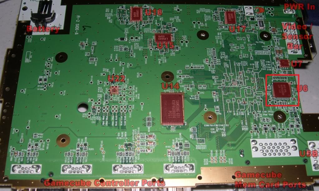
here is the data i had put together so far..
the AVE chip contains all the pin connections required for the MX B012355 board except for 12V and 54MHz..
- 12v is only required for the D-Terminal Cable. The voltage is reduced on the MX board to provide a reduced 5v data signal to trigger this type of TV to display video as interlaced or progressive...
- 54MHz was traced back to the MX RTC chip and should be a suitable solution..
i would be interested to know how Tchay cut his board for the Envision to determine if the filters were removed..
if so, then this would make conversion easier......as long as the IPL doesnt provide an issue..
i imagine some of the Resistor and Capacitors i have listed below should be for S- video and PAL RGB, maybe someone can help fill in the gaps


- Attachments
-
- AVE_N-DOL PINOUT.JPG
- (932.92 KiB) Not downloaded yet
-
- AVE_N-DOL-001.JPG
- (731.12 KiB) Not downloaded yet
>>> BadAssConsoles.com <<<emu_kidid wrote: beer is like WD40 for megalomaniac's brain, gets the gears moving

Re: Gamecube component cable
PAL boards DO have different A/V chips than NTSC boards, which is why we fight to get Luigi's Mansion ntsc to work with the Wiikey. The PAL version boots, but the video is handled incorrectly by the NTSC A/V chip. :/
Re: Gamecube component cable
did anybody ever try a transplant??Ashen wrote:PAL boards DO have different A/V chips than NTSC boards, which is why we fight to get Luigi's Mansion ntsc to work with the Wiikey. The PAL version boots, but the video is handled incorrectly by the NTSC A/V chip. :/
please search before you ask - a lot has been discussed already!
(or use google with "site:gc-forever.com *term*")
http://is.gd/MDmZcr
we also have a wiki filled with knowledge
http://is.gd/dX58Rm
(or use google with "site:gc-forever.com *term*")
http://is.gd/MDmZcr
we also have a wiki filled with knowledge
http://is.gd/dX58Rm
Re: Gamecube component cable
Yea, Zenloc did at one point. I forget exactly what he said the results were. But I do remember him saying that the video still wasn't right.
A thought stuck me the other day about transplanting a Wii A/V chip to the GC. I think if we could figure out what signals are what on the Wii chip and match them up to the GC it would solve the problem of the high priced component cable AND the Luigi's Mansion problem all in one shot. PAL Luigi's Mansion IS displayed correctly when booted on the Wiikey Fusion on the Wii. You can pick up a "broken" wii on ebay for about 30 beans. Much better than $100+ for a GC dterminal or component cable.
EDIT:
Here is the Wii A/V Chip:
being that the Wii truley is just a GC v1.5 more so than previously thought, I'm 99% sure a transplant is possible. Just need a pinout.
- Attachments
-
- Wii_mb_btm.jpg
- (149.52 KiB) Not downloaded yet
Re: Gamecube component cable
megalomaniac wrote:Wow, thanks for the info..Durgan wrote:Actually there's a digital signal bus that can be tapped into on any GameCube; you don't need a revision A cube to have component.Benni wrote:I´m also interested!
BUT - I there is no digital out on my GC!
First I need a way to get a digital out!
I've been thinking about making a brief post on the GC's video outputs. But now I'm thinking that a larger, more-encompassing thread would be pretty useful. I haven't seen a lot of focus on the matter and I think there's a lot of interest out there in it.
the AVE chip is the same in both DOL-001 and DOL-101..
It certainly does appear possible to solder leads to the AVE chip to allow those without a digital port to wire up a MX chip...
I have not had the time to try this on a DOL-101, and i also wondered if it was even going to work because of possible IPL issues not allowing 480p...
just like the PAL GC does not output S-Video and the NTSC GC does not output RGB...could this be controlled by the IPL or do PAL GC's have a different AVE chip?
I havnt done enough research on it yet, but i have been looking for a PAL GC to maybe help me draw some conclusions
here is the data i had put together so far..
the AVE chip contains all the pin connections required for the MX B012355 board except for 12V and 54MHz..
- 12v is only required for the D-Terminal Cable. The voltage is reduced on the MX board to provide a reduced 5v data signal to trigger this type of TV to display video as interlaced or progressive...
- 54MHz was traced back to the MX RTC chip and should be a suitable solution..
i would be interested to know how Tchay cut his board for the Envision to determine if the filters were removed..
if so, then this would make conversion easier......as long as the IPL doesnt provide an issue..
i imagine some of the Resistor and Capacitors i have listed below should be for S- video and PAL RGB, maybe someone can help fill in the gaps
Nice! I hadn't been able to find those pinouts yet. Where did you get them? I'll be sure to include this info in the thread I'm making.
I don't think imposing limitations on progressive display would be in the IPL's job description, but there might be registers elsewhere that prevent it. Interlaced display would certainly still be possible though, and I would guess progressive would (at least on NTSC cubes) but I don't know for sure. PAL GCs should have the same AVE chip as all the others, I'll go into this more as a response to both you and Ashen.
There may be different revisions of the A/V chips, just as there are different revisions of the MX chip, but the hardware is essentially the same. They simply operate in different modes, which is software dependent. This is why the transplant mod mentioned above didn't work, because the new chip was being told to do the same thing as the old one.Ashen wrote:PAL boards DO have different A/V chips than NTSC boards, which is why we fight to get Luigi's Mansion ntsc to work with the Wiikey. The PAL version boots, but the video is handled incorrectly by the NTSC A/V chip. :/
I'm writing up a more in-depth explanation of all of this right now. Unfortunately I may have to leave before I finish and complete this when I come back in a day or two.
-
megalomaniac
- Posts: 2480
- Joined: Sun Aug 21, 2011 5:33 am
- Location: Drunk in Texas
- Contact:
Re: Gamecube component cable
i was looking for pinouts also but could not find any...Durgan wrote: Nice! I hadn't been able to find those pinouts yet. Where did you get them? I'll be sure to include this info in the thread I'm making.
so i simply pinned out the chip and created these photos..feel free to use them...
>>> BadAssConsoles.com <<<emu_kidid wrote: beer is like WD40 for megalomaniac's brain, gets the gears moving
Re: Gamecube component cable
I have no doubt there are different revisions of the A/V chip. That doesn't have anything to do with the fact that PAL and NTSC A/V chips are different though. I know this for fact, not just theory. PAL chips output RGB natively, NTSC chips output s-video. It has nothing to do with software. Its a hardware thing. The chips are also labeled differently. NTSC chips are AVE N-DOL, PAL chips are AVE E-DOL.
-
megalomaniac
- Posts: 2480
- Joined: Sun Aug 21, 2011 5:33 am
- Location: Drunk in Texas
- Contact:
Re: Gamecube component cable
Durgan wrote:
I don't think imposing limitations on progressive display would be in the IPL's job description, but there might be registers elsewhere that prevent it. Interlaced display would certainly still be possible though, and I would guess progressive would (at least on NTSC cubes) but I don't know for sure. PAL GCs should have the same AVE chip as all the others, I'll go into this more as a response to both you and Ashen.
There may be different revisions of the A/V chips, just as there are different revisions of the MX chip, but the hardware is essentially the same. They simply operate in different modes, which is software dependent. This is why the transplant mod mentioned above didn't work, because the new chip was being told to do the same thing as the old one.Ashen wrote:PAL boards DO have different A/V chips than NTSC boards, which is why we fight to get Luigi's Mansion ntsc to work with the Wiikey. The PAL version boots, but the video is handled incorrectly by the NTSC A/V chip. :/
I'm writing up a more in-depth explanation of all of this right now. Unfortunately I may have to leave before I finish and complete this when I come back in a day or two.
please do not get discouraged by the following....
but i question where you data comes from...i assume this is just a theory since you state "its possible" and you "guess"
also you indicate the AV chips operate in different modes due to software..what software?? the game title or the IPL?
im most certain Zenloc tried both NTSC and PAL versions of Luigi Mansion as per proper testing of his transplant...
if this is strictly hardware, then perhaps zenloc may have had better testing results after a hardware only transplant..Ashen wrote:I have no doubt there are different revisions of the A/V chip. That doesn't have anything to do with the fact that PAL and NTSC A/V chips are different though. I know this for fact, not just theory. PAL chips output RGB natively, NTSC chips output s-video. It has nothing to do with software. Its a hardware thing. The chips are also labeled differently. NTSC chips are AVE N-DOL, PAL chips are AVE E-DOL.
i am still suspicious that the IPL is also partially part of the problem
one thing we can all agree on is both NTSC and PAL units can use the component cable...
as for the DOL-101..well there is only one way to find out
>>> BadAssConsoles.com <<<emu_kidid wrote: beer is like WD40 for megalomaniac's brain, gets the gears moving
Re: Gamecube component cable
Zenloc wrote:The wiikey does not support forcing video mode unlike the wode which does. The av chip of a ntsc board does not support pal composite signals that's why the image doesn't look right nor does the resolution. It's the same on pal boards altough they do show the right colours with a ntsc signal. The resolution however will be 480 cropped in a 576 resolution giving you a big black bar on the bottem of the screen and squishing the image.
switching av chip won't work I alreadt tried that. Nor does it work with switching any other components. I tried swapping the av chip and both clock chips and nothing give you proper pal and ntsc signals on one board.
Any of you have other idea's??
-
megalomaniac
- Posts: 2480
- Joined: Sun Aug 21, 2011 5:33 am
- Location: Drunk in Texas
- Contact:
Re: Gamecube component cable
i dont see a 54mhz clock on the DOL-101, i hope that RTC point i pinned out on the DOL-001 will still work...
gonna try it anyways...if anything, i should get at a minimum interlaced YPBPR
here goes nothing...
gonna try it anyways...if anything, i should get at a minimum interlaced YPBPR
here goes nothing...
>>> BadAssConsoles.com <<<emu_kidid wrote: beer is like WD40 for megalomaniac's brain, gets the gears moving
Re: Gamecube component cable
Mega, as you can see here:
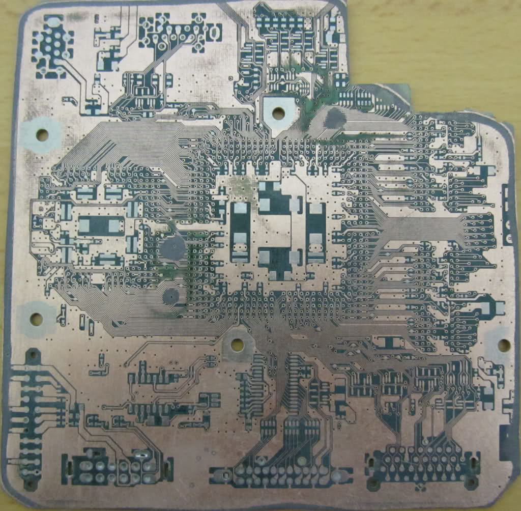
All the data signals used for component output go straight from the GPU to the connector for the digital A/V port. If you're not getting a signal on a rev C cube, theoretically you should trace it back to the GPU on a rev A/B board and use the same spot for a rev C. Hope that helps.
All the data signals used for component output go straight from the GPU to the connector for the digital A/V port. If you're not getting a signal on a rev C cube, theoretically you should trace it back to the GPU on a rev A/B board and use the same spot for a rev C. Hope that helps.
- Attachments
-
- 1z1z5z6.jpg
- (165.87 KiB) Not downloaded yet
-
megalomaniac
- Posts: 2480
- Joined: Sun Aug 21, 2011 5:33 am
- Location: Drunk in Texas
- Contact:
Re: Gamecube component cable
looks like a no go for now....
double checked all wiring and nothing....
thanks ashen, ill give that a shot another day

double checked all wiring and nothing....
thanks ashen, ill give that a shot another day
>>> BadAssConsoles.com <<<emu_kidid wrote: beer is like WD40 for megalomaniac's brain, gets the gears moving
Re: Gamecube component cable
The only uncertainty was specifically noted. The rest of what I'm saying is each from different sources I have bookmarked from across the net (I can give specifics on stuff if you want). The best explanation I've found about the DAC's modes is in patent information for the GC, here, page 86, line 10. You can find a list of other various GC patents in the references section of this document: http://zelda64rus.ucoz.ru/_fr/1/yagcd.pdf (which itself also has a lot of good information).megalomaniac wrote: please do not get discouraged by the following....
but i question where you data comes from...i assume this is just a theory since you state "its possible" and you "guess"
also you indicate the AV chips operate in different modes due to software..what software?? the game title or the IPL?
im most certain Zenloc tried both NTSC and PAL versions of Luigi Mansion as per proper testing of his transplant...
The software I'm referring to would basically be the GC OS, bootloaders/Bootstrap-Stage/IPL, and whatever else may be contained in the various ROMs in the system.
Trying different versions of the game wouldn't do anything because it's the system itself that is configured to be a certain region system.
The chips receive information alongside the timing signals of the YCbCr video stream for what it should be converting the video to (it's sent on the CbCr data lines during the vertical blanking period). So what the DAC outputs is actually dependent on variables "keys" that the GPU lays out. [Check out the link and page I linked to above on the patent info.] The part of the GPU that handles its own video output (and finishes creation of the signal) is called the video interface. It too is capable of operating in different modes. Also look on page 87 of that same patent doc, just before the table. The variables that describe the mode are called "registers" (for some reason it doesn't explain it there, but "VI" stands for "video interface"). Where the "registers" are stored, however, or how to change them, I do no know. Have you been able to find any other specific information about these chips?Ashen wrote:I have no doubt there are different revisions of the A/V chip. That doesn't have anything to do with the fact that PAL and NTSC A/V chips are different though. I know this for fact, not just theory. PAL chips output RGB natively, NTSC chips output s-video. It has nothing to do with software. Its a hardware thing. The chips are also labeled differently. NTSC chips are AVE N-DOL, PAL chips are AVE E-DOL.
I say that the chips are essentially the same in terms of hardware because they should be capable of the same things. If I'm right, you should be able to take a working NTSC set-up (TV/cube/game combo), replace the DAC with one from a PAL system, and everything will continue to work fine (the DAC will still output NTSC Composite + S-Video). The new DAC will simply listen to the timing signals from the Flipper and operate in the respective mode. I might try it myself if I had a PAL cube to take apart.
Re: Gamecube component cable
I could be completely wrong here (coming from a software side of things), but the hardware itself should be exactly the same. In writing homebrew/etc, I've tested video modes by configuring the Video Interface to different types on different hardware and all work (meaning the hardware is the same across regions). I.e. NTSC on PAL, and PAL on NTSC (some were complaining PAL on NTSC didn't work on Wii).

Re: Gamecube component cable
I'm pretty damn sure the audio/video chips are different internally. Both chips take the raw signals from the GPU (the same signals that go direct to the digital port) and convert them to composite, s-video(NTSC) or rgb(PAL).
if you look at mega's pinout:
NTSC chips output composite on pin 25
PAL chips output composite on pin 23
So as you can see, the pinouts between the two chips are (slightly) different.
Also, I was wrong about the label of the PAL chips, I looked at my two PAL boards I have last night.
PAL chips are labeled: AVE P-DOL
NTSC chips are labeled AVE N-DOL
EDIT:
I also did a quick test of the grounding points of the chip on the output side:
PAL A/V Chip Pinout:
32 - Ground
31
30
29
27 - Ground
26
25
24 - Ground
23 - Composite out
22 - Ground
21 - Ground
20 - R Audio
19 - Ground
18
17 - L Audio
NTSC A/V Chip Pinout:
32 - Ground
31
30
29
27
26
25 - Composite out
24
23 - Ground
22 - Ground
21 - Ground
20 - R Audio
19 - Ground
18
17 - L Audio
Re: Gamecube component cable
Yeah, I've read that they output composite on different pins, but that could be changeable based on the mode as well. The main thing that I find strange is the N-DOL/P-DOL difference (I mean the printing on the chip and what manufacturing differences they indicate). But Emu Kidid's work with homebrew by configuring the video interface corroborates what I'm saying. So I'm pretty confident that the swap experiment I mentioned would work. Though I am sill a little curious to see it. I assume, btw, that Zenloc's attempt was assuming there would be a change in output, so he was looking for a signal using the wrong kind of TV. (Anyone want to try it? Like I said, I'd probably try it myself if I had a PAL DAC.)
So, Emu Kidid, you know about those registers I mentioned? Is that what you changed via homebrew, or to be more accurate, is their change a result of changing something else maybe? I know there are lots of sources on homebrew, but where can I find out more about this matter in particular? I've never used homebrew myself so it would be good if any explanation starts from the basics.
So, Emu Kidid, you know about those registers I mentioned? Is that what you changed via homebrew, or to be more accurate, is their change a result of changing something else maybe? I know there are lots of sources on homebrew, but where can I find out more about this matter in particular? I've never used homebrew myself so it would be good if any explanation starts from the basics.
Last edited by Durgan on Mon Jan 23, 2012 10:54 pm, edited 1 time in total.
Re: Gamecube component cable
Durgan, you basically just write values to the register block mentioned here: http://gc-forever.com/yagcd/chap5.html#sec5.3
In libOGC this is all done transparently in VIDEO_Init() and VIDEO_Configure(mode);
In libOGC this is all done transparently in VIDEO_Init() and VIDEO_Configure(mode);