To make a long story short, I have read on the wiki about the XenoGC and about making my own clone
You know, whats the fun in buying one when you can make your own?
The only problem is that I have no experience in programming chips
I read on the wiki about building your own programmer, but my computer doesn't have a Serial/Parallel Port and the USB programmer seems overly complicated (and not that fun) to build. I found this on ebay for cheap.
Questions:
1:Would this programmer work?
It comes with "10 pin ISP interface"
This leads me to my next question:
2:How would i connect the programmer to my chip? The homemade programmers in the wiki have a few pins sticking out of the board, but I couldn't fiind any information about how to connect it. Maybe I'm missing something obvius...
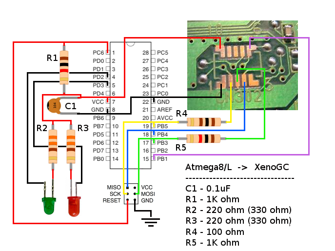
3: What chip should I use? I read that the Atmega8L is the same as the original Xeno. But Atmega8A is cheaper. (The names are links to the cheapest on Ebay
Thats my main concerns right now. Thanks for reading and thanks for an awesome forum!