Page 1 of 1
IDE - EXI Serial Port 1 (BBA)
Posted: Wed Mar 07, 2012 3:12 pm
by Jaecus
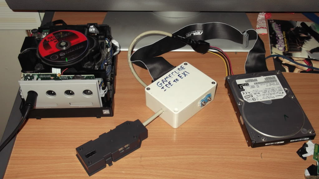
Following the recent arival of my Tri-wing screwdriver I set about working on this project..
To turn my working Memory Card style IDE-EXI into Serial Port 1(BBA) style IDE-EXI
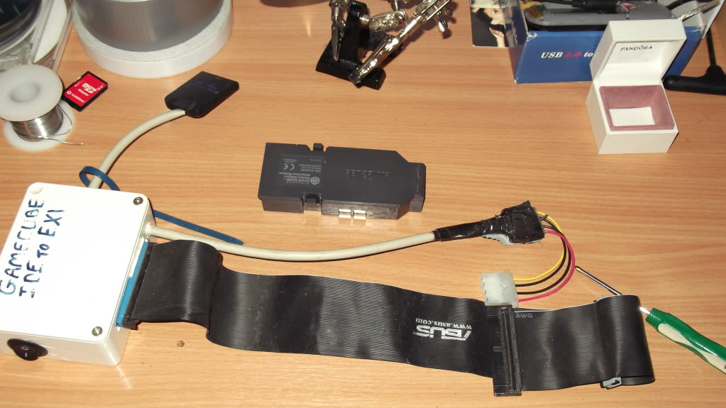
So far I have:-
-Snapped off the curcuit of the Modem Adapter leaving enough to hold the connector in place with the original 4 screws
-Dremmeled out some plastic where my wire exits the adapter
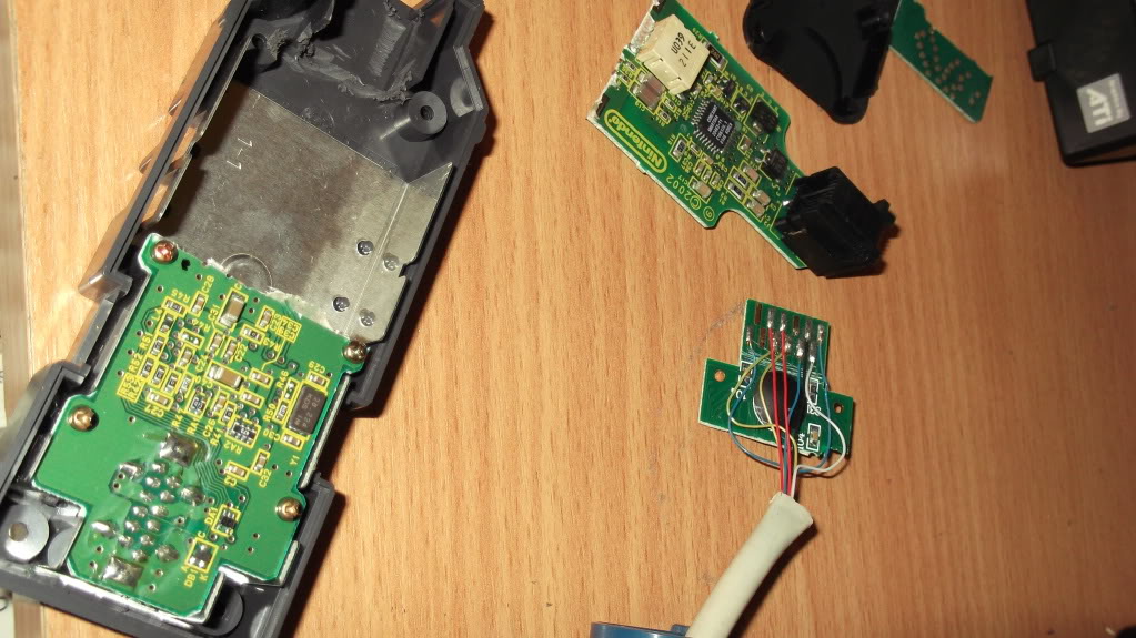 But in relation to my Modem adapter's Circuit, looking down on it in above picture which would be pin 1?
Also I have noticed in memorycard we bridge EXTIN and EXTOUT however in BBA there is no EXTout so this means it will work with no bridge or any other circuitry kept in the Modem side?
YAGCD wrote:2.4.1.4 BBA/Modem Connector (P6)
pin Signal
1 EXTIN
2 Ground (Shield)
3 INT
4 CLK
5 12V
6 DO
7 3.3V
8 3.3V
9 DI
10 CS
11 Ground
12 Ground
my next step is to desolder from my memorycard adapter and switch to these pins in the above YAGCD quote.
YAGCD wrote:2.4.1.1 Memory Card Slots (P4,P5)
pin Signal
1 EXTIN
2 GND
3 INT
4 3.3V
5 DO
6 5V
7 DI
8 3.3V
9 CS
10 Ground (Shield)
11 CLK
12 EXTOUT
Re: IDE - Serial Port 1 (BBA)
Posted: Wed Mar 07, 2012 4:08 pm
by _Nold_
For detecting pin 1: Just check which pin goes to GND

Nice work so far

Re: IDE - Serial Port 1 (BBA)
Posted: Thu Mar 08, 2012 6:49 am
by dilav
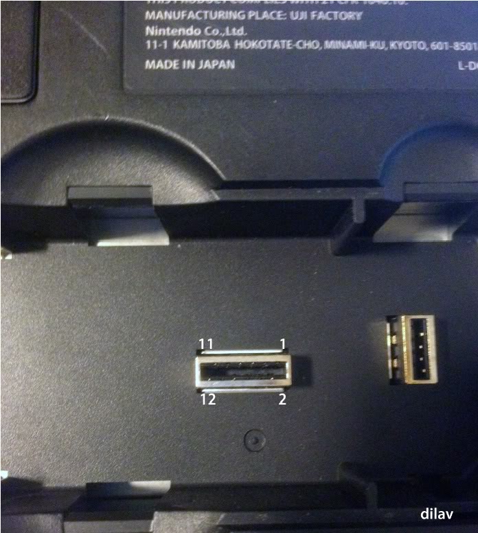
Bridging 1 and 12 on the memory card tells the GC that a memory card is in. Have no clue about the BBA.
Re: IDE - Serial Port 1 (BBA)
Posted: Thu Mar 08, 2012 9:00 pm
by Jaecus
very helpful thank you.
Right now i really dont want to mess this part up!!..
I have soldered the EXI wires up (excluding HDD power lines)
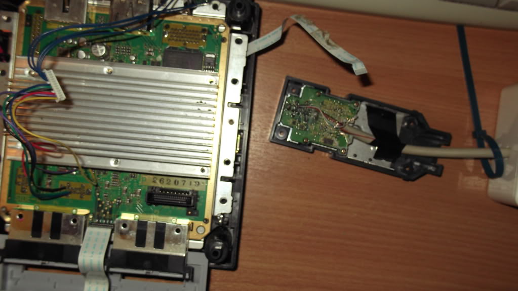
Next, in order to achieve HDD 5v I need to replace a pin trace. Any unused pin is fine baring in mind I also have Qoob Pro Installed here. I plan to replace pin 7(currently unused 3.3v) with 5v.. whats the best way? megalomaniac suggested I cut the trace, can anybody guide me specifically? maybe a pic of a sanded down board could indicate the spot to cut...
After that, adding 5v from a suitable point should be easy, just a wire from GC power pins.
Can anybody confirm on the sense pin EXTIN and suggest what would be a sensible thing to try in order to trick GC into thinking BBA is present?
other than these minor issues, I'm ready to test BBA_IDE-EXI with swiss!
Re: IDE - Serial Port 1 (BBA)
Posted: Thu Mar 08, 2012 11:43 pm
by megalomaniac
Looking from the top view, pin 7 and 8 are connected together...
it looks like you could cut the trace to pin 8 and be fine soldering a 5v wire to it...
or you might be able to use one of the GND pins 2, 11, 12...
Top View
 Bottom View

Re: IDE - Serial Port 1 (BBA)
Posted: Fri Mar 09, 2012 1:34 am
by Jaecus
Thanks again for the help Megalomaniac!
ok!.. all solder'd up and ready!.. or is it?
It looks the part and now my 5v mod seems to have worked as it now powers my Qoob too, as the original fidly job came loose, however I am unsure if I have properly cut the trace between pins 7 & 8.. I can't seem find my multimeter :s
powering the cube with the adapter plugged in shorts the cube out. now how to solve tricking the sense?
Re: IDE - Serial Port 1 (BBA)
Posted: Fri Mar 09, 2012 1:43 am
by emu_kidid
Qoob needs 3.3v doesn't it? (could be wrong)
Edit: I'm re-working IDE-EXI stuff at the moment in Swiss so you should have a configurable port to use the bottom two slots too.
Re: IDE - Serial Port 1 (BBA)
Posted: Fri Mar 09, 2012 1:58 am
by Jaecus
emu_kidid wrote:Qoob needs 3.3v doesn't it? (could be wrong)
Edit: I'm re-working IDE-EXI stuff at the moment in Swiss so you should have a configurable port to use the bottom two slots too.
qoob also has 5v(red cable) which suggests to use a precarious solder point below a resistor.
Great!.. Swiss pwns!
Re: IDE - EXI Serial Port 1 (BBA)
Posted: Fri Mar 09, 2012 2:19 am
by megalomaniac
the qoob should have about a 20k or 30k resistor inline with 5v lead for protection
how to know if your trace cut is successful??
maybe disconnect the 5v lead for now and test the trace cut pin for power using an LED...
...hmmm...then figure out what to do about sense....
who is the chick in a bra at the top right corner of the pic??
Re: IDE - EXI Serial Port 1 (BBA)
Posted: Fri Mar 09, 2012 3:26 am
by Ashen
Sense is simply 3.3v going to whatever pin needs it.
On the memcard ports pin 1 gets 3.3v via a bridge on the memcard to pin 12. It should be the same in this case if I'm not mistaken, just input 3.3v to ext in
Re: IDE - EXI Serial Port 1 (BBA)
Posted: Fri Mar 09, 2012 11:34 am
by Jaecus
great tips thanks guys
Re: IDE - EXI Serial Port 1 (BBA)
Posted: Sat Mar 10, 2012 4:28 pm
by Benni
little question:
What´s going on here?
Do you want to create a new IDE Interface for the GC or do you just want to use the IDE-Exi AND both mem-slots?
Maybe the BBA/Modem Port is faster for IDE-EXI?
AND:
Is it possible to use YOUR IDE-EXI AND BBA?
THX
Re: IDE - EXI Serial Port 1 (BBA)
Posted: Sun Mar 11, 2012 12:19 am
by emu_kidid
BBA/Modem port is the same in speed.
IDE-EXI and BBA at the same time is possible if the IDE-EXI is in the Memcard slot of course :p
Re: IDE - EXI Serial Port 1 (BBA)
Posted: Sun Mar 11, 2012 10:07 am
by Benni
Yes, i know this!
I have IDE-Exi AND BBa...
i thought, if BBA-port is faster maybe there is a way to use both.
So this is only for fun!
Re: IDE - EXI Serial Port 1 (BBA)
Posted: Fri Apr 13, 2012 11:25 pm
by dilav
Just curious what happen to this test?
Is there a test build of swiss that support IDE/SD Gecko on Serial Port 1?
Re: IDE - EXI Serial Port 1 (BBA)
Posted: Sat Apr 14, 2012 1:08 am
by emu_kidid
Not yet but this is high on my endless to do list