Page 1 of 1
Homemade XenoGC Clone questions
Posted: Tue Jun 12, 2012 11:34 pm
by WatsuG
Hello!
To make a long story short, I have read on the wiki about the XenoGC and about making
my own clone
You know, whats the fun in buying one when you can make your own?

The only problem is that I have no experience in programming chips

and have a few questions. I want this to be the cheap as possible because I can.

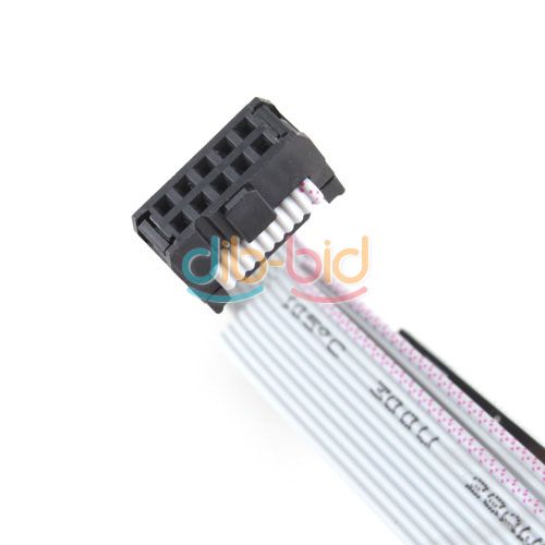
I read on the wiki about building your own programmer, but my computer doesn't have a Serial/Parallel Port and the USB programmer seems overly complicated (and not that fun) to build. I found
this on ebay for cheap.
Questions:
1:Would
this programmer work?
It comes with "10 pin ISP interface"
This leads me to my next question:
2:How would i connect the programmer to my chip? The homemade programmers in the wiki have a few pins sticking out of the board, but I couldn't fiind any information about how to connect it. Maybe I'm missing something obvius...

3: What chip should I use? I read that the
Atmega8L is the same as the original Xeno. But
Atmega8A is cheaper. (The names are links to the cheapest on Ebay
) They both operate on the same voltage. Do the more expensive Atmega8L have any advantages over the cheaper Atmega8A?
Thats my main concerns right now. Thanks for reading and thanks for an awesome forum!
Re: Homemade XenoGC Clone questions
Posted: Wed Jun 13, 2012 12:26 am
by megalomaniac
the purpose to chose atmega8L over atmega8 is only because the 8L is able to operate at 3.3v....atmega8 requires 5v..
whats this mean is the long run?
with 8L you can use normal 3.3v at the regular serial port drive location...@ 8mhz speed
with 8 you need to pull 5v from another location...@ 16mhz speed
thats it...thats the only difference between those two chips...
now with the atmega8A
http://www.atmel.com/Images/AVR523.pdf
the change log indicates
1. atmega8A is basically identical to the atmega8
2. but also capable of operating at 3.3v like the atmega8L except @ 4mhz...
based on this data, my analysis indicates the 8A could be a safe substitute as long at 4mhz is fast enough...(it should be)
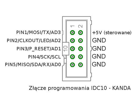
to program the chip you can use a 6 pin or 10 pin...
just compare the 10pin signal vs 6pin signals using a google image search and match up the appropriate connections...
any more questions, ask
good luck
Re: Homemade XenoGC Clone questions
Posted: Wed Jun 13, 2012 6:29 am
by SouLSLayeR
If I had to guess I'd say it's just your 6 normal ISP pins and the rest are NCs or GND.
(nice find btw I am currently doing exactly the same thing

)
edit: bullseye

 http://www.micro4you.com/files/avrpro/usbasp.pdf
Re: Homemade XenoGC Clone questions
Posted: Wed Jun 13, 2012 8:52 am
by WatsuG
Thanks for the quick answers!
So its okay to use the 10 pin connector
But how would i connect the 10 pin connector to a chip with 28 legs? I might still miss something obvius...
I mean the physical connection. Should I just solder some wires to the appropiate pins on the chip?
I have seen development boards with connections for all kinds of chips
Thanks again
EDIT:
I saw this in the wiki. Its the xeno with reprogrammable ISP
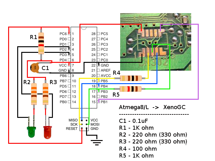
On the bottom in the middle theres a pic of a 6pin connector and how its wired in parallel with the chip. Do this mean I just wire:
SCK-PB5 pin on chip
MISO-PB4
MOSI-PB3
and ground and voltage? I know where these are on the 10 pin connector thanks to SouLSLayeR
I mean when I'm programming the chip, not when its in the cube.
I can make a picture in paint if its hard to understand what I mean

Re: Homemade XenoGC Clone questions
Posted: Wed Jun 13, 2012 9:51 am
by SouLSLayeR
And don't forget to wire RST to GND so the chip can enter programming state.
You could connect a simple on-off switch before the resistor that goes from RST to Vcc.
When the switch is ON, then the RST will be connected directly to ground so you will be able to program the chip.
When the switch is OFF, the RST will be connected to Vcc through the resistor, and the chip will function normally.
Re: Homemade XenoGC Clone questions
Posted: Thu Jun 14, 2012 12:05 am
by megalomaniac
you can use either a 6pin or 10pin cable...
just make sure to match up the connections appropriately
....if it becomes too confusing, take another look on ebay because some of those usb programmers also come with a 6pin cable
Re: Homemade XenoGC Clone questions
Posted: Fri Jun 15, 2012 12:44 am
by WatsuG
I just ordered a programmer and two Atmega8a on ebay. The shipping will probably take half a month:/
Also, can I program playstation modchips with this kind of programmer? Maybe this isn't the right forum, you guys just seem to have alot of knowledge about stuff like that
I read
here on Eurasia that its possible to use a 12F629 chip. They are cheap on ebay

I just don't know anything about flashing chips... (yet
)
Re: Homemade XenoGC Clone questions
Posted: Fri Jun 15, 2012 2:19 am
by megalomaniac
WatsuG wrote:I just ordered a programmer and two Atmega8a on ebay. The shipping will probably take half a month:/
Also, can I program playstation modchips with this kind of programmer? Maybe this isn't the right forum, you guys just seem to have alot of knowledge about stuff like that
I read
here on Eurasia that its possible to use a 12F629 chip. They are cheap on ebay
I just don't know anything about flashing chips... (yet
)
you might need to use another programmer or another programming software compatible with the programmer you have...
i only have experience with AVR/atmega using avrdude
if it is possible, then i wouldnt know since i wont touch a pic
Re: Homemade XenoGC Clone questions
Posted: Fri Jun 15, 2012 8:53 am
by SouLSLayeR
I got a Willem programmer some months ago.
Around 25 euros.
Probably a not -so- good choice, as you can get a cheap ass
USB programmer with some euros more, and the difference is amazing.
Solely the USB is worth it XD
You can't imagine the horrors of LPT1

At least it programs PICs too, not only EEPROMS and FLASH memories.
Back on topic, as you found ISP programmers for AVRs on ebay, you should find for PICs too.
Re: Homemade XenoGC Clone questions
Posted: Tue Jul 31, 2012 11:55 pm
by WatsuG
I programmed my chip last night and wired it up. The pics made it look so easy, with big solderpoints. The solderpoints turned out to be tiny and a real pain to solder. But i think I made it. However when I start my gamecube up the red led flashes a little and then turn red.
Wiki wrote:NOTE: Check installation if no LED activity or constant Red LED.
I have checked my wiring and I cant find anything that might be wrong. I have tested a little with a multimeter.
If I start the cube and try to read i disc i get an error.
Gamecube wrote:An error has occured. Turn the power of and refer to the Nintendo Gamecube instruction booklet for further instructions.
I don't think the instruction booklet will give me much info on how to get my modchip working
Holding start doesn't bring up the menu or do anything. I flashed the chip with XenoAT.hex that was in the Xeno source folder.
Say plumbum if you want pictures
Does anyone know whats wrong/what I did wrong or have any tips?
Thanks in advance
Re: Homemade XenoGC Clone questions
Posted: Wed Aug 01, 2012 12:18 am
by emu_kidid
Red means the XenoGC was unable to successfully patch your drive from all I know. Does it flicker randomly or in a consistent pattern?
If it's randomly, I'd say it's a connection problem. Usually it's meant to go Red->Quick Flicker->Green(or orange on clones).
Re: Homemade XenoGC Clone questions
Posted: Wed Aug 01, 2012 12:29 am
by megalomaniac
the chip appears functional since its indicating red led meaning failed patch upload..
double check your soldering points...
make sure you have the chip pins to the correct pads on the drive...
if you have it wired right, then make sure you are not using some crazy length of wiring...
one more thing to consider, did you set the fuses on the chip to C4 & D9??
i see you also are using an Atmega8A...
as i stated, from the data sheets it should be a direct drip in replacement...but has never been tested..
Re: Homemade XenoGC Clone questions
Posted: Wed Aug 01, 2012 12:34 am
by WatsuG
Thanks for the quick reply
I used IDE ribbon cable and I think it might have been a little thick, meaning the solder didnt cover it enough. I think its called cold joint. I found some thinner wires in my wirebox so I will try to rewire it tomorrow. Hopefully its a connection problem.
How about the error code? Is that because Xeno couldn't patch the drive? And did I use the right hex to flash the chip?
I didn't set any fuses. I didn't know that was neccesary. Maybe I should reflash the chip?
EDIT: How long should the wires be? Mine are 10-15 cm
Re: Homemade XenoGC Clone questions
Posted: Wed Aug 01, 2012 1:26 am
by megalomaniac
wire length is fine....
ide wire can break internally...or just give bad overall connection...
use kynar solid core wire whenever possible...
your flash is fine...set your fusebits as described in the wiki
dont glob the solder and try again
Re: Homemade XenoGC Clone questions
Posted: Wed Aug 01, 2012 1:49 am
by WatsuG
I just rewired it. Doesn't work. Still red light.
Took wires the same colours as in your guide
I'm going to bed now. I'll have to look at this tomorrow. Maybe I just wired somthing wrong again...
Re: Homemade XenoGC Clone questions
Posted: Wed Aug 01, 2012 1:57 am
by megalomaniac
can you also include a close up pic of the solder points on the drive
nice clear pic if possible...
Re: Homemade XenoGC Clone questions
Posted: Wed Aug 01, 2012 8:54 am
by WatsuG
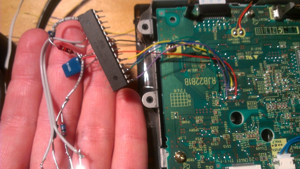
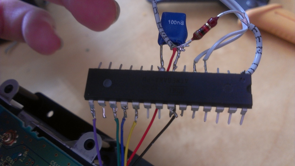
Heres the chip.
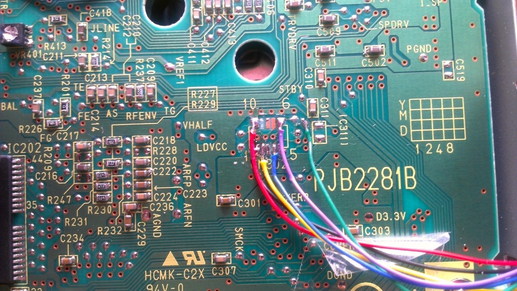
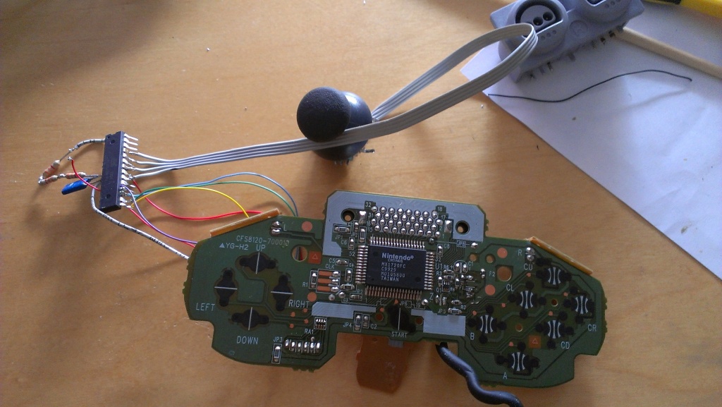
And heres the driveboard
I broke off my voltage pin

Could that be causing the problems? I soldered a cable to what was left of the pin and it seems to make a connection. I have no way to test though...
Re: Homemade XenoGC Clone questions
Posted: Wed Aug 01, 2012 10:19 am
by emu_kidid
black and yellow look like they might be shorted together
Re: Homemade XenoGC Clone questions
Posted: Wed Aug 01, 2012 11:35 am
by WatsuG
I just tested with my multimeter and they werent shorted. Is setting the fuses important?
Re: Homemade XenoGC Clone questions
Posted: Wed Aug 01, 2012 1:33 pm
by dilav
100nS? This is a Capacitor?
Yes setting fuses can be very important.
Re: Homemade XenoGC Clone questions
Posted: Wed Aug 01, 2012 5:41 pm
by megalomaniac
pad 2 and 3 look like there might be solder contact...
try moving lead wire of pad 2 & 4 to the alternate solder points like you did with 3
this will help ensure no crossover contact is made and clean up pads 2/3/4 just to make sure...
if this still dont work, unsolder the chip, set those fusesbits...then connect everything again and see what happens...
Re: Homemade XenoGC Clone questions
Posted: Mon Aug 20, 2012 8:07 pm
by WatsuG
I sadly scrapped this when it wasnt working
I 'm pretty sure the reason for it not working was that I didnt set the fuses. I reprogrammed the chip and set the fuses correctly and now it works
. However its not an Xeno anymore... I flashed it so I can use PSX analogs with a N64 controller that I will use in my portable.
I will try again to make me a xeno now that i know how to program chips
I just need more microcontrollers