hello,
i was throwing together a basic "really basic" pcb design for a gamecube to ffc adapter that sits under the board and basically dose everything..
i posted it on one of my forums so people could tidy up the design, and it was pointed out a similar board already exists..
I noticed the similar board sits on the top and needs you to remove components.
so i thought id add it here as maybe some one could improve it and it would be usefull to the community as it would requier very little skill to install.
if it was made to the scale of the holes on the gamecube's pcb it would sit flush on the board and not get in the way.
it has 3.3v supplied to pin 32.
2 pads for the eject button. and then a 1.9v and ground pad close together for wii dvd drive replacment NC switches..
like i said it was really basic and i put it together fast so double check it.
its in the very 1st "thought" stage.
do with it as you wish.
Wiikey - GC pcb
-
shambles1980
- Posts: 10
- Joined: Sun Sep 01, 2013 10:54 pm
Wiikey - GC pcb
- Attachments
-
- GCwikiPcb.jpg
- (147.41 KiB) Not downloaded yet

Re: Wiikey - GC pcb
kennycc made an adapter that does exactly this, it's not so easy to solder to under the board either unless if you can get a super thin PCB happening.

-
megalomaniac

- Posts: 2480
- Joined: Sun Aug 21, 2011 5:33 am
- Location: Drunk in Texas
- Contact:
Re: Wiikey - GC pcb
the design to make bottom mount is fairly easy to accomplish...
a few pointers to improve the design:
1. the layout have does not provide enough ideal room for the ffc connector and the jumps shown between the FFC connector pins and the DVD connector pins..having those jumps there will take up valuable space in a very limited mainboard footprint..
2. there is a GND trace passing between pin 23 and 24...this is impractical and maybe unsafe
the pins are ~.2mm width, the pads ~.3mm width, and each pin has .5mm on center spacing
that means you would need a .1mm GND trace with .05mm spacing on each side
that is a very very very thin trace going to the regulators..either the trace will burn up or the regulators will not provide proper power
3. regulators should be repositioned to another location due to nearby components on the mainboard...
the regulators could provide interference to the nearby filters...
4. suggest using an upper pin FFC connector to ensure proper clearance of the nearby capacitors in that area..
5. the biggest problem with a bottom mount design is the existing solder on the DVD connector port
if you look at the bottom of the mainboard where the dvd connector is soldered, the solder is "domed"
this means each pcb needs to have domed insets drilled at all the points to allow the PCB to have a flush mount..
part of the problem is not all the solder is a uniform shape...so getting a flush mount is far from a perfect process...
6. as emu_kidid said the pcb needs to be very very thin to allow the pins to pass thru the board to make soldering easier...
i have already made a bottom mount design and sent it as a special one-off build for another forum member...
i was not happy with the bottom mount design even though i had already optimized my version will all the points listed above...
good luck
>>> BadAssConsoles.com <<<emu_kidid wrote: beer is like WD40 for megalomaniac's brain, gets the gears moving
Re: Wiikey - GC pcb
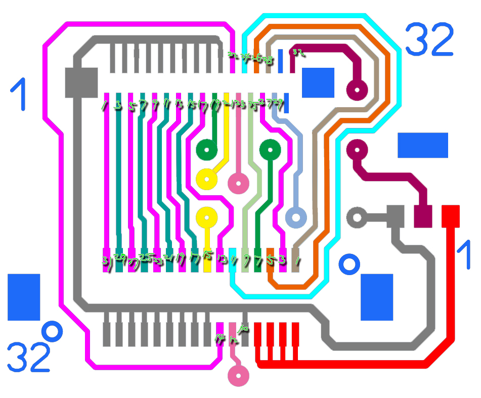
Use NGC DVD drive interfaces and FFC
DIY PCB
DIY PCB
- Attachments
-
- 试制的PCB.png
- (712.93 KiB) Not downloaded yet
-
- 原理图.jpg
- (360.64 KiB) Not downloaded yet
-
shambles1980
- Posts: 10
- Joined: Sun Sep 01, 2013 10:54 pm
Re: Wiikey - GC pcb
I think that pcb is connecting 5v directly to ground..
I may not be reading it properly but it looks like 5v is going to ground
(1st ground pin to the right. next to where you connect 22/23)
thats if im understanding the pcb.
I may not be reading it properly but it looks like 5v is going to ground
(1st ground pin to the right. next to where you connect 22/23)
thats if im understanding the pcb.
-
megalomaniac
- Posts: 2480
- Joined: Sun Aug 21, 2011 5:33 am
- Location: Drunk in Texas
- Contact:
Re: Wiikey - GC pcb
@glf999
you got the right idea....just need a to go back and read the component datasheet first....
also check your spacings all over the board because what you propose there will be impossible for real world use....
you got the right idea....just need a to go back and read the component datasheet first....
also check your spacings all over the board because what you propose there will be impossible for real world use....
>>> BadAssConsoles.com <<<emu_kidid wrote: beer is like WD40 for megalomaniac's brain, gets the gears moving
Re: Wiikey - GC pcb
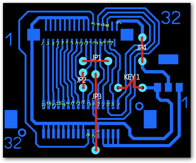
抱歉 前几天的原理图 没有标出飞线 和开关的位置
A few days ago sorry not marked schematics fly line and switch position
今天补上一个图片
Today added something a picture
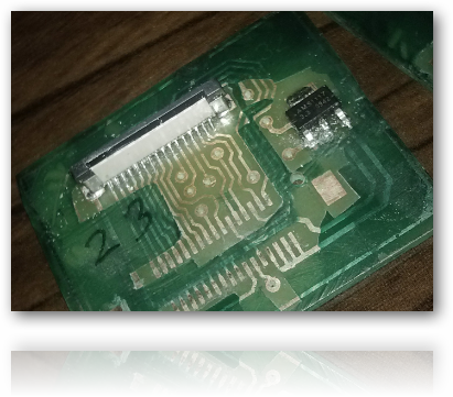
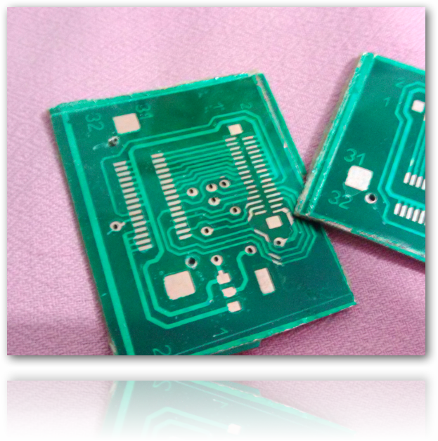
已经做好好几天了
Ready for several days
并且安装了 Swiss 214 自启动
And installed Swiss 214 Autoboot
A few days ago sorry not marked schematics fly line and switch position
今天补上一个图片
Today added something a picture
已经做好好几天了
Ready for several days
并且安装了 Swiss 214 自启动
And installed Swiss 214 Autoboot
- Attachments
-
- 线路图.png
- (69.42 KiB) Not downloaded yet
-
- anzhuang2.png
- (474.82 KiB) Not downloaded yet
-
- 贴装完毕的PCB.png
- (266.25 KiB) Not downloaded yet
-
- test gc wii 4-1.rar
- PCB File Ues Sprint-Layout 6.0 edit or print
- (5.06 KiB) Downloaded 391 times
-
shambles1980
- Posts: 10
- Joined: Sun Sep 01, 2013 10:54 pm
Re: Wiikey - GC pcb
i see in this image
the trace is cut so 5v is not going direct to ground any more
But now 5v is going to pin 29...
Im 99% sure that thats 5v right there because its the mistake i made with my dvd plugin connector..
i only counted 4 5v points when there are 5..
-= Edit =-
actually shut my face.
There are 4 5v points the 5th is a ground.
so that connection is fine.
Turns out i counted the correct ammount of 5v points all along. i just missed out a ground.