3D render of the prototype board.
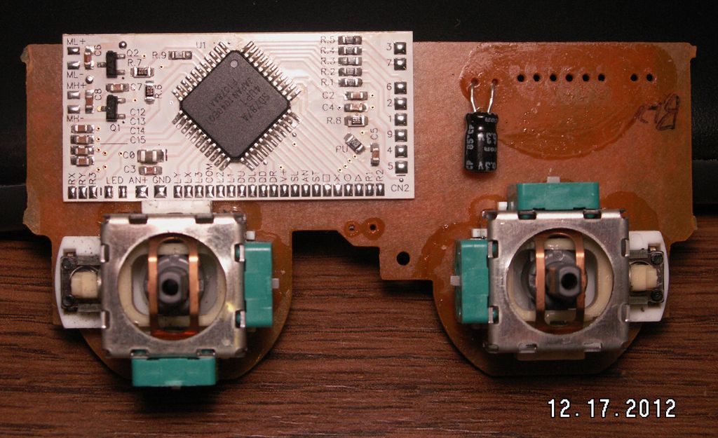
Then after it was made and most of the parts swapped over from a donor controller.
The prototype there is missing quite a few things, mostly decoupling caps, but also a couple of solder pads for the Analog voltage power and ground, couple for the Ground for the button pads and it needed a footprint change for Q3. They weren't necessary for a first run, and I was interested in getting the prototype done quickly for testing, but they have all been placed on the final revision of the PCB. The prototype there also has the larger Resonator and C1, which will be swapped out for the smaller SMT versions. Some of the wired GC controllers already have the SMT Resonator, but this one didn't.
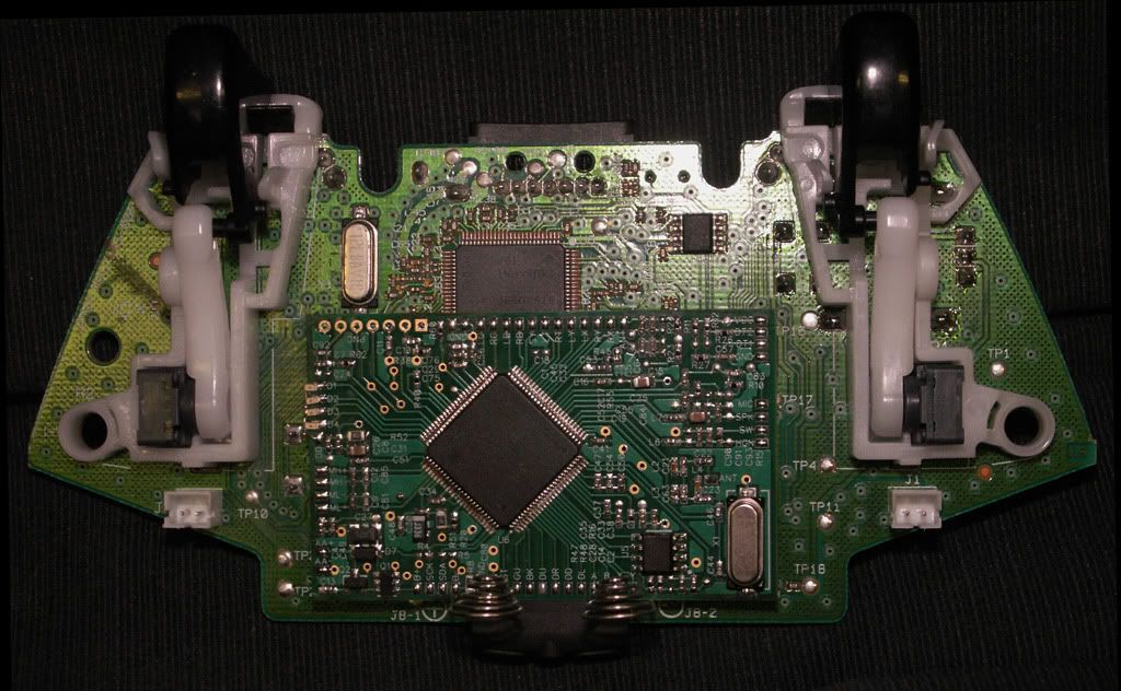
Some Sticks, Trigger sliders and the motor wired up for testing.
Everything works like it's supposed to. The PCB is 25mm x 50mm, so it's not quite as small as the miniDS2, but not a heck of a lot bigger either. All of the parts were kept on one side so the PCB also.
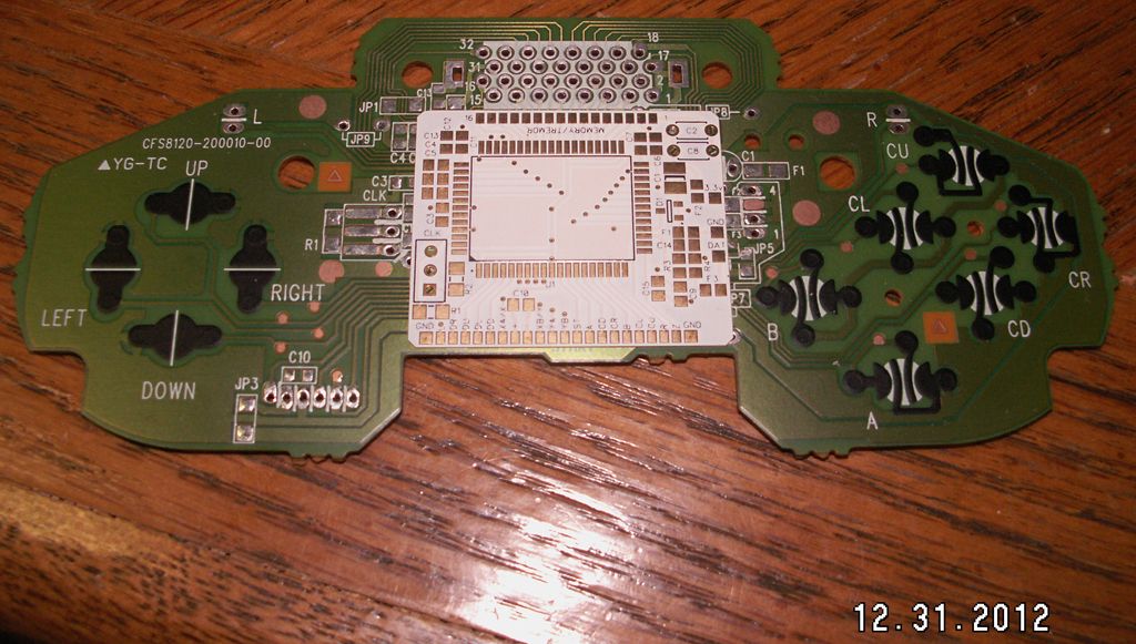
3D render of the final PCB for the miniGC with the decoupling caps and Analog power spots added.


