Portables, case replacements, mods etc, all in here!
-
|RDC|
- Posts: 39
- Joined: Thu Mar 21, 2013 9:38 pm
Post
by |RDC| » Thu Nov 14, 2013 10:37 pm
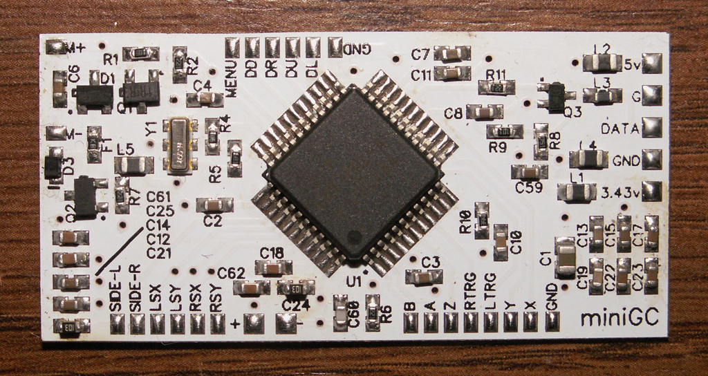
Boards are here now. I'm not thrilled to death with the silk job on them, they offset it for some reason and it's faded in some places on some board. They're not as pretty as they could be, but they're still functional.
Blank board
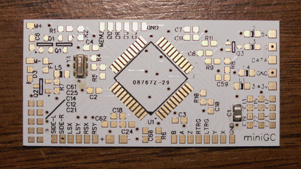 Full board
 (with 10k Resistors installed in parallel at C21 and C24 for Digital Slides)
-
Attachments
-
- miniGCRev1SlideMod_zpse18bb3f0.jpg
- (668.03 KiB) Not downloaded yet
-
- miniGCRev1_zps9e97c824.jpg
- (635.94 KiB) Not downloaded yet
Screwing up is one of the best learning tools, so long as the only thing you're not learning is how to screw up.
-
megalomaniac
- Posts: 2480
- Joined: Sun Aug 21, 2011 5:33 am
- Location: Drunk in Texas
-
Contact:
Post
by megalomaniac » Fri Nov 15, 2013 3:29 am
ill volunteer to receive the worst looking board of the batch...
that full board pic you posted should be good enough to use as a guide, but could you also post up the new render too just in case...
-
|RDC|
- Posts: 39
- Joined: Thu Mar 21, 2013 9:38 pm
Post
by |RDC| » Fri Nov 15, 2013 4:16 am
There is no new render. The last 3D render in the very first post is this board.
Screwing up is one of the best learning tools, so long as the only thing you're not learning is how to screw up.
-
megalomaniac
- Posts: 2480
- Joined: Sun Aug 21, 2011 5:33 am
- Location: Drunk in Texas
-
Contact:
Post
by megalomaniac » Fri Nov 15, 2013 4:32 am
ahhh...ok my mistake...
i was looking at the prototype render...
-
|RDC|
- Posts: 39
- Joined: Thu Mar 21, 2013 9:38 pm
Post
by |RDC| » Fri Nov 15, 2013 4:49 am
No problem.
Another thing that can also vary from board to board is F1. There is an 0603 sized one (small) and a 1210 one (large). If any donor board has the larger 1210 sized
F1, that will not fit on this board, it was made for the 0603 as that was the board I designed this from and the few others I had to look at here all were the same.
I didn't know about the larger one until a few days ago when I received some more controllers to work on. It's a 0.7A (700mA) fuse if anyone is really wanting
to replace it with an 0603 size, but if you're not using the Rumble then it's not needed, or if you are using the Rumble and don't have the smaller 0603 size one
on your donor board, just jumper wire it, the likelihood of it ever doing it's job is slim to none.
Screwing up is one of the best learning tools, so long as the only thing you're not learning is how to screw up.
-
megalomaniac
- Posts: 2480
- Joined: Sun Aug 21, 2011 5:33 am
- Location: Drunk in Texas
-
Contact:
Post
by megalomaniac » Fri Nov 15, 2013 5:12 am
"should" be able to solder F1 at an angle if need be
looks like there might be plenty of pad to make the necessary contact at an angle...
or maybe even try to tombstone it slightly
-
liquitt
- Posts: 1814
- Joined: Thu Apr 01, 2010 5:43 am
- Location: neverland
Post
by liquitt » Tue Nov 19, 2013 8:45 am
nice work dude!
please search before you ask - a lot has been discussed already!
(or use google with "site:gc-forever.com *term*")
http://is.gd/MDmZcr
we also have a wiki filled with knowledge
http://is.gd/dX58Rm
-
zefeldo
- Posts: 1
- Joined: Thu May 16, 2013 6:36 pm
Post
by zefeldo » Sat Jan 03, 2015 11:03 pm
I know this is a very old forum but is there any more of these available?
-
|RDC|
- Posts: 39
- Joined: Thu Mar 21, 2013 9:38 pm
Post
by |RDC| » Sun Jan 04, 2015 8:52 am
Yes there are. PM me what you're looking for.
Screwing up is one of the best learning tools, so long as the only thing you're not learning is how to screw up.
-
EDGNEZ
- Posts: 1
- Joined: Sun Jun 07, 2015 4:30 pm
Post
by EDGNEZ » Sun Jun 07, 2015 4:37 pm
do you still sell these boards?? a blank board works fine.
-
|RDC|
- Posts: 39
- Joined: Thu Mar 21, 2013 9:38 pm
Post
by |RDC| » Mon Jun 08, 2015 11:03 am
I still have a couple of blank PCBs around. You can PM me for details.
Screwing up is one of the best learning tools, so long as the only thing you're not learning is how to screw up.
-
andre104623
- Posts: 694
- Joined: Wed May 07, 2014 2:24 pm
Post
by andre104623 » Thu Jun 11, 2015 12:46 pm
I would also take 2. Oh this is old sorry
-
|RDC|
- Posts: 39
- Joined: Thu Mar 21, 2013 9:38 pm
Post
by |RDC| » Thu Jun 11, 2015 1:09 pm
I have 2 blank boards available, if you're interested you can PM me.
Screwing up is one of the best learning tools, so long as the only thing you're not learning is how to screw up.
-
andre104623
- Posts: 694
- Joined: Wed May 07, 2014 2:24 pm
Post
by andre104623 » Mon Jun 15, 2015 8:00 pm
|RDC| wrote:I have 2 blank boards available, if you're interested you can PM me.
Got the board they look great and there really small very nice. Thank you
-
|RDC|
- Posts: 39
- Joined: Thu Mar 21, 2013 9:38 pm
Post
by |RDC| » Tue Jun 16, 2015 12:18 am
Welcome, any issues or questions let me know.
Screwing up is one of the best learning tools, so long as the only thing you're not learning is how to screw up.
-
andre104623
- Posts: 694
- Joined: Wed May 07, 2014 2:24 pm
Post
by andre104623 » Tue Jun 16, 2015 1:18 pm
|RDC| wrote:Welcome, any issues or questions let me know.
My donor board has F1 as a 1210 size instead of the 0603? size that is on the MINIGC. Is everything else the same?

So far this is what I got done
-
|RDC|
- Posts: 39
- Joined: Thu Mar 21, 2013 9:38 pm
Post
by |RDC| » Tue Jun 16, 2015 3:27 pm
You can make it fit there, or just toss it and jumper F1 as it's only for the Rumble motor and I've never seen one go bad. Rest is the same.
Screwing up is one of the best learning tools, so long as the only thing you're not learning is how to screw up.
-
andre104623
- Posts: 694
- Joined: Wed May 07, 2014 2:24 pm
Post
by andre104623 » Tue Jun 16, 2015 6:20 pm
|RDC| wrote:You can make it fit there, or just toss it and jumper F1 as it's only for the Rumble motor and I've never seen one go bad. Rest is the same.
Yep your right I can make it fit. After 3 1/2 hours labor its done finally. Need to test and clean (and maybe move D1 over a little)
-
andre104623
- Posts: 694
- Joined: Wed May 07, 2014 2:24 pm
Post
by andre104623 » Tue Jun 16, 2015 9:09 pm
Tested the minigc just had rumble motor, A, and left stick wired up seems to work OK I'm proud of myself only one controller donor. I'm usually not good at desoldering and resoldering but worked out fine and I have a extra also which is good. Thank you very much since I bought your last 2 will you make your Gerber files public so anyone could order a few boards at a later time?
Oh there are two points at the bottom of the minigc labeled + and - obviously - is ground but the + is 3.3 volts correct for the analog sticks
-
|RDC|
- Posts: 39
- Joined: Thu Mar 21, 2013 9:38 pm
Post
by |RDC| » Tue Jun 16, 2015 9:50 pm
Correct, the + and - at the bottom of the PCB is for the Analog Sticks as well as the Sliders, SIDE-R and SIDE-L as they are Analog as well.
I have no plans to release the Gerber files currently. You only bought the last 2 that I currently had made up and were ready to be sold. I still have a few more boards here that just need the Xtal and C1 installed and can be sold as blank boards, or populated for complete ones. After those are gone though, if any more are needed I'll just do a redesign with any changes, improvements or such and order some more up.
Screwing up is one of the best learning tools, so long as the only thing you're not learning is how to screw up.
-
andre104623
- Posts: 694
- Joined: Wed May 07, 2014 2:24 pm
Post
by andre104623 » Tue Jun 16, 2015 9:58 pm
|RDC| wrote:Correct, the + and - at the bottom of the PCB is for the Analog Sticks as well as the Sliders, SIDE-R and SIDE-L as they are Analog as well.
I have no plans to release the Gerber files currently. You only bought the last 2 that I currently had made up and were ready to be sold. I still have a few more boards here that just need the Xtal and C1 installed and can be sold as blank boards, or populated for complete ones. After those are gone though, if any more are needed I'll just do a redesign with any changes, improvements or such and order some more up.
Cool, I very much like the way it is already but anyway thank you for the swift service and support.
-
|RDC|
- Posts: 39
- Joined: Thu Mar 21, 2013 9:38 pm
Post
by |RDC| » Wed Jun 17, 2015 12:06 am
Welcome.
Screwing up is one of the best learning tools, so long as the only thing you're not learning is how to screw up.
-
andre104623
- Posts: 694
- Joined: Wed May 07, 2014 2:24 pm
Post
by andre104623 » Thu Jun 18, 2015 2:55 pm
|RDC| wrote:Welcome.
Hey you got anymore 3ds2an boards I was looking at other people's portables to give me some insight and I saw a board called 3ds2an. After some digging I found that you make the PCB how convenient. So let me know
-
|RDC|
- Posts: 39
- Joined: Thu Mar 21, 2013 9:38 pm
Post
by |RDC| » Thu Jun 18, 2015 4:21 pm
Currently I do not have 3DS2AN boards made up, though I do have a few PCBs here and just need to order the components, flash the PIC and populate the PCB to have one ready to go. You can PM me for details there.
Screwing up is one of the best learning tools, so long as the only thing you're not learning is how to screw up.
-
andre104623
- Posts: 694
- Joined: Wed May 07, 2014 2:24 pm
Post
by andre104623 » Fri Jun 19, 2015 10:18 pm
I have a problem now. I hooked up the minigc with analog left and right, A, B, Start, rumble motor and booted up the wiikey into swiss. I selected resident evil 4 and booted up to the menu screen and when I pressed A to start a new game the rumble motor came on then that was it. The minigc will not take any inputs at all now I have no idea why it was working fine I think that was the first time the rumble motor ever turned on in the minigc. Any ideas anyone or is my IC chip fried