Hello,
Just looking to get some help with GC portable power wiring. I know these boards work because they come from badassconsoles.
I've wired it using shockslayers TI regulator wiring diagram. 1.9v 3.3v 5v
I've also wired it as a trimmed board right to the components even though it's not trimmed yet using Ashens method. 1.9v 3.3v 5v and GND
I wired 1.9v to both spots as his diagram indicates. The power supply i'm using is a 7.4V 1.2A battery charger from battery space.
I'm using a multiout cable to get video on my TV and all i get is a garbled grey and black image that flashes on and off.
Looking to get a bid of assistance and can provide pictures if needed. I do have some experience making portables as i'm almost completed my n64p case painting left.
Thanks,
Ice
Portable Wiring Help
Re: Portable Wiring Help
Yeah can I see some pics of the work. I need clear pics please.
Re: Portable Wiring Help
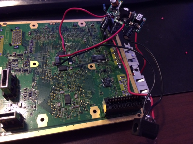
I ended up bridging it on the power port for the time being 1.9v that is.
Remember this is only to make sure the console powers up...testing the regulators and PSU. Everything is putting out the correct voltages.
Remember this is only to make sure the console powers up...testing the regulators and PSU. Everything is putting out the correct voltages.
- Attachments
-
- image2_zpsrpxvpwcj.jpg
- (88.45 KiB) Not downloaded yet
-
- image1_zpsadi3eot3.jpg
- (128.29 KiB) Not downloaded yet
Re: Portable Wiring Help
So this ended up being amperage...i fixed it by buying a 2.5A PSU.
Everything worked fine before my OMGWTF cut. I have a few boards to mess around with, so i wanted to try this one out first...I think the next one i might do the cut before this one.
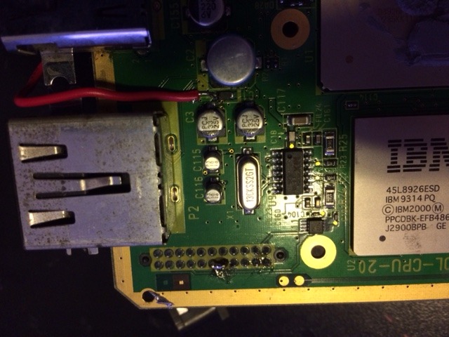
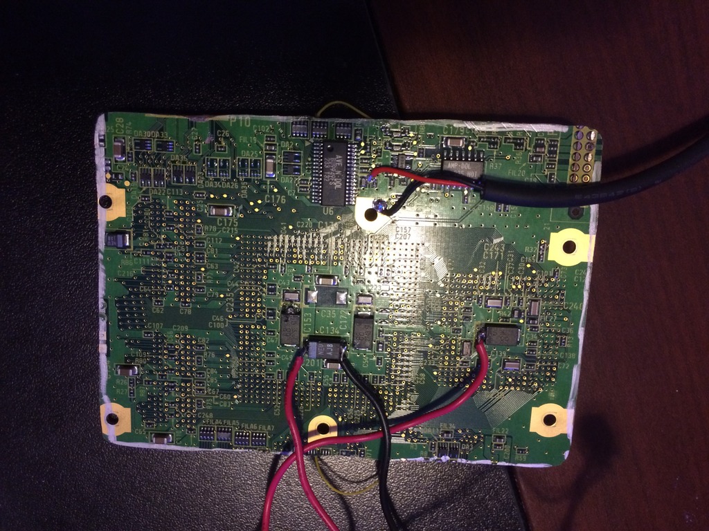
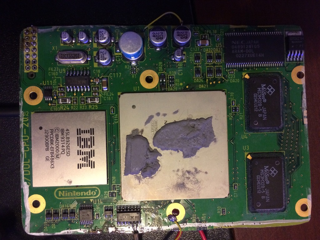
Anyway, I did the the and am not getting any video on the screen. I feel the IBM chip getting hot...but not the other one. I checked my voltages and everything looked fine. I did sand the edges quite well after the cut as well. I reconnected the crystal and also the composite filter cap. I do see low voltages coming out of the composite cable, but no image. I read over the guide a few times, but feel like i am missing something. Something else i did was i left a bit of excess board. I don't know if this effects anything.
Here are pictures.
Everything worked fine before my OMGWTF cut. I have a few boards to mess around with, so i wanted to try this one out first...I think the next one i might do the cut before this one.
Anyway, I did the the and am not getting any video on the screen. I feel the IBM chip getting hot...but not the other one. I checked my voltages and everything looked fine. I did sand the edges quite well after the cut as well. I reconnected the crystal and also the composite filter cap. I do see low voltages coming out of the composite cable, but no image. I read over the guide a few times, but feel like i am missing something. Something else i did was i left a bit of excess board. I don't know if this effects anything.
Here are pictures.
- Attachments
-
- image_zpsmbtetzzb.jpg
- (241.65 KiB) Not downloaded yet
-
- image_zpsctze5yyi.jpg
- (278.38 KiB) Not downloaded yet