Gamecube component cable
Re: Gamecube component cable
man i really have to lurk on modretro and benheck a lot more than i do 8)
please search before you ask - a lot has been discussed already!
(or use google with "site:gc-forever.com *term*")
http://is.gd/MDmZcr
we also have a wiki filled with knowledge
http://is.gd/dX58Rm
(or use google with "site:gc-forever.com *term*")
http://is.gd/MDmZcr
we also have a wiki filled with knowledge
http://is.gd/dX58Rm
Re: Gamecube component cable
Cool. I was hoping he would add that at some point.Ashen wrote:marshallh wrote:
small update, I did a board respin some time ago
Currently moving to a single DVI-I connector that'll let you use an adapter to get both VGA and HDMI if you want them
tbh, I hadn't checked in on benheck in ages.
I'll get in touch with Marshall, I'm sure he could add GC support.
OzOnE.

Re: Gamecube component cable
Or just bug the aforementioned people in other ways for status updatesliquitt wrote:man i really have to lurk on modretro and benheck a lot more than i do 8)

Re: Gamecube component cable
Just a "quick" chime-in to say that the basic GC Digital AV code is working on the FPGA. 
No HDMI output yet, as it needs to be modified to work with the GC's interlaced output.
I'm just sorting out a modchip for this PAL GC too, so I can use progressive mode via HDMI.
Basically it's running from the Digital AV output via the FPGA then out to VGA on my dev board.
(It's using some sigma-delta DAC code for the VGA testing, so it's a bit fuzzy atm, understandably).
It is also outputting YPrPb (component style) colour, but my old Pioneer plasma can switch to component colour space so I can see it properly.
The Pioneer also supports interlaced via the VGA socket, which is a bit hit-and-miss these days. lol
It will need a YCrCb to RGB code block for proper RGB / VGA output, but the image is perfectly stable (apart from the above mentioned fuzzy stuff).
So, we now know the Digital Vid interface isn't so mysterious after all.
Sorry, no photos just yet, need some sleep first (it's 5am here now), but here's the first SigTap capture...
http://i40.tinypic.com/2ynq63q.jpg
And here's a better one with the flags / sync stuff added...
http://i39.tinypic.com/33ehc1k.jpg
btw, on the gamesx pinout, the "ClkSelect" signal is actually called "vphase" or "VICR" in the GC patent.
When this signal is HIGH, you grab the Cr byte after Y.
When it's LOW, you grab the Cb byte after Y.
As described in the patent / gamesx; when the "Y" byte equals 0x00 (right after "vphase" toggles), the Cr / Cb bytes then denote the "flag" bytes.
You can then extract the various sync / flag bits...
A "gc_blank" flag can be set when Y == 0x00 as well.
The 54MHz and 27MHz clock outputs from the GC are normally free-running, so it's the just actual pixel rate which changes to 54MHz for prog mode (dependant on the software, as mega dude reminded me.).
The above captures were with interlaced mode ofc, so this is a 27MHz pixel rate (that "DVI_PLL" signal is 27MHz).
EDIT: Technically, the "pixel" rate in interlaced mode is only 13.5MHz as you'd expect, 'cos there's only one "Y" (luminance) byte for every two 27MHz clocks.
Each of the colour difference signals is only half the sampling rate (6.25MHz) of the luminance . This is a VERY common SD video sampling standard.
Early days yet, but thought I'd leave an update if anyone's interested?
Can't promise a that finished product will definitely, but I'm hoping this will at least lead to something nice.
(Might work on non-Dig AV GC's as well, but soldering to the DAC won't be easy.)
OzOnE.
No HDMI output yet, as it needs to be modified to work with the GC's interlaced output.
I'm just sorting out a modchip for this PAL GC too, so I can use progressive mode via HDMI.
Basically it's running from the Digital AV output via the FPGA then out to VGA on my dev board.
(It's using some sigma-delta DAC code for the VGA testing, so it's a bit fuzzy atm, understandably).
It is also outputting YPrPb (component style) colour, but my old Pioneer plasma can switch to component colour space so I can see it properly.
The Pioneer also supports interlaced via the VGA socket, which is a bit hit-and-miss these days. lol
It will need a YCrCb to RGB code block for proper RGB / VGA output, but the image is perfectly stable (apart from the above mentioned fuzzy stuff).
So, we now know the Digital Vid interface isn't so mysterious after all.
Sorry, no photos just yet, need some sleep first (it's 5am here now), but here's the first SigTap capture...
http://i40.tinypic.com/2ynq63q.jpg
And here's a better one with the flags / sync stuff added...
http://i39.tinypic.com/33ehc1k.jpg
btw, on the gamesx pinout, the "ClkSelect" signal is actually called "vphase" or "VICR" in the GC patent.
When this signal is HIGH, you grab the Cr byte after Y.
When it's LOW, you grab the Cb byte after Y.
As described in the patent / gamesx; when the "Y" byte equals 0x00 (right after "vphase" toggles), the Cr / Cb bytes then denote the "flag" bytes.
You can then extract the various sync / flag bits...
Code: Select all
gc_inter_n 	 <= vdata[0]; // I
gc_pal 		  <= vdata[1]; // M
gc_burst_blank <= vdata[2]; // K
gc_burst 		<= vdata[3]; // B
gc_hsync_n	  <= vdata[4]; // H
gc_vsync_n	  <= vdata[5]; // V
gc_field 		<= vdata[6]; // F
gc_csync_n <= vdata[7]; // CThe 54MHz and 27MHz clock outputs from the GC are normally free-running, so it's the just actual pixel rate which changes to 54MHz for prog mode (dependant on the software, as mega dude reminded me.).
The above captures were with interlaced mode ofc, so this is a 27MHz pixel rate (that "DVI_PLL" signal is 27MHz).
EDIT: Technically, the "pixel" rate in interlaced mode is only 13.5MHz as you'd expect, 'cos there's only one "Y" (luminance) byte for every two 27MHz clocks.
Each of the colour difference signals is only half the sampling rate (6.25MHz) of the luminance . This is a VERY common SD video sampling standard.
Early days yet, but thought I'd leave an update if anyone's interested?
Can't promise a that finished product will definitely, but I'm hoping this will at least lead to something nice.
(Might work on non-Dig AV GC's as well, but soldering to the DAC won't be easy.)
OzOnE.
Last edited by OzOnE on Fri May 10, 2013 4:41 am, edited 8 times in total.
-
megalomaniac

- Posts: 2480
- Joined: Sun Aug 21, 2011 5:33 am
- Location: Drunk in Texas
- Contact:
Re: Gamecube component cable
hehe..thought you were going to sleep already 
>>> BadAssConsoles.com <<<emu_kidid wrote: beer is like WD40 for megalomaniac's brain, gets the gears moving

Re: Gamecube component cable
Well shit, I'm excited.
Re: Gamecube component cable
Me too, but you know what it's like. lolmegalomaniac wrote:hehe..thought you were going to sleep already
Thought I was gonna settle down to watch yet another Mythbusters,
but had to settle for "Destroyed In Seconds", or that boring American Chopper junk. *ducksforcover*
(actually, when I first saw "American Chopper" advertised, I thought it was porn. How disappointed I was.)
Did I mention I'll be trying a laptop panel at some point.
Re: Gamecube component cable
EDIT: Re-posted in the new thread, so as not to hijack this one.
-
megalomaniac
- Posts: 2480
- Joined: Sun Aug 21, 2011 5:33 am
- Location: Drunk in Texas
- Contact:
Re: Gamecube component cable
update...
i only have a few MEGA3 PCB's left...but i still have more chips so i can make some homemade PCBs...i cant get a small production run on the few chips i have remaining...
there will also be a few changes to make installation a lot more user friendly for almost anyone....
no details yet...im still working out the specifics....
>>> BadAssConsoles.com <<<emu_kidid wrote: beer is like WD40 for megalomaniac's brain, gets the gears moving

Re: Gamecube component cable
Hi megalomaniac! Too bad I found out about your mod only today as I would order one of those PCBs. I hope you're still working on this thing because it's amazing. Now if only somebody could reverse engineer the MX chip and make a cheaper equivalent... I hate when people charge for an official component cable over 300 dollars. It's insane. That's why I think your work is so important. I hope you will make more in the future. Good luck!

Re: Gamecube component cable
I'm sure making a fpga solution is doable I have no idea how difficult it is I've never tried this sort of thing. A modder (furrtek) recently found a way to convert the digital video signals of the virtualboy into something your tv will accept:
http://www.youtube.com/watch?v=CCqky6sZ_R0
FPGA wizardry is lovely, I just wish I didn't hate programming.
http://www.youtube.com/watch?v=CCqky6sZ_R0
FPGA wizardry is lovely, I just wish I didn't hate programming.
-
ChristianMswanson

- Posts: 6
- Joined: Sun Aug 04, 2013 9:58 pm
Re: Gamecube component cable
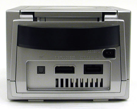
Is there an Instructional guide or images for an Internal mod? Or more importantly is an internal mod possible? I really do not want to compromise my component cable. Im thinking along the lines of installing a port next to the digital A/V like so
- Attachments
-
- GCFO_zps30007019.png
- (215.14 KiB) Not downloaded yet
-
megalomaniac
- Posts: 2480
- Joined: Sun Aug 21, 2011 5:33 am
- Location: Drunk in Texas
- Contact:
Re: Gamecube component cable
i assume you are talking about an audio mod....
viewtopic.php?f=26&t=1236
viewtopic.php?f=26&t=1236
>>> BadAssConsoles.com <<<emu_kidid wrote: beer is like WD40 for megalomaniac's brain, gets the gears moving
-
ChristianMswanson
- Posts: 6
- Joined: Sun Aug 04, 2013 9:58 pm
Re: Gamecube component cable
Any pics of it installed in the GC?megalomaniac wrote:here is the fiber optic board..
this will be the stand alone board for anyone who wants to add internal fiber optic audio only..(no video)
im my opinion, it may be easier to add this board to the GC with only 5wire connections to the mobo rather than disassemble the component video cable...
i have disassembled 3 component cables already and the metal shielding must be bent to remove and access the video board.
then 5wires must be connected to the video board...on top of this, the tricky part is to bend the metal shielding back into the original shape (or close enough to original shape) in order to properly close the plastic housing...
although this may or may not be a simple task, i dont have the patients to mess with the shielding long enough...
i dont have pics of the metal shielding readily available but im sure you all know what im referring to...
anyone who wishes to add external fiber optic audio to the component cable will have a slightly different board design with just a few more components, and must also mod the component cable housing to allow the wires to pass thru from the video board to the audio board..
at the same time, the GC housing must be modified for the internal board to add the FO connector...
i would think it may be easier for most to mod the GC case itself disassemble the component cable shielding and reassemble and then mod the component cable housing..
note = when i say easier, thats because im lazy
some notes about the internal audio only board:
the internal design uses stacked components to save board space and make the design as small as possible...
i needed to minimize the footprint of the audio board to allow me to use it on the video board also...
...so this design is used for both internal audio boards only and full audio/video boards too...(with small differences in circuit pathways, but same footprint)
here is the lower layer of components..
74HC04 hex inverter
3 capacitors
12.2880 crystal
0 ohm jumper
and 2 jumper wires
...and here is finished product
TC9231N
47uF capacitor
and super glue on the jumper wires just in case


-
megalomaniac
- Posts: 2480
- Joined: Sun Aug 21, 2011 5:33 am
- Location: Drunk in Texas
- Contact:
Re: Gamecube component cable
that pic is a prototype
look at the link i posted above with instructions from kel01
look at the link i posted above with instructions from kel01
>>> BadAssConsoles.com <<<emu_kidid wrote: beer is like WD40 for megalomaniac's brain, gets the gears moving
Re: Gamecube component cable
Great guides like that need more sticky.
-
ChristianMswanson
- Posts: 6
- Joined: Sun Aug 04, 2013 9:58 pm
Re: Gamecube component cable
I'm assuming you will build some kind of enclosure for all of this? or will it fit in the GC?
Last edited by ChristianMswanson on Tue Aug 06, 2013 6:08 am, edited 1 time in total.
-
ChristianMswanson
- Posts: 6
- Joined: Sun Aug 04, 2013 9:58 pm
Re: Gamecube component cable
megalomaniac wrote:i assume you are talking about an audio mod....
viewtopic.php?f=26&t=1236
ahh yes..sorry i just now read this.. this is what i was looking for
Re: Gamecube component cable
Will you ever rebuild new Mega3 boards?
-
RagingAvatar

- Posts: 1
- Joined: Sat Apr 27, 2013 9:06 am
Re: Gamecube component cable
Hi guys,
I know I'm very late to the party..
Basically, I want to get digital video out for my Gamecube - how can I get hold of the parts, cables.. whatever, to achieve this?
Is megalomanic still making things that achieve this?
If so, what's the process of buying it?
I know I'm very late to the party..
Basically, I want to get digital video out for my Gamecube - how can I get hold of the parts, cables.. whatever, to achieve this?
Is megalomanic still making things that achieve this?
If so, what's the process of buying it?
-
inspectah_deck
- Posts: 32
- Joined: Mon Jun 25, 2012 10:25 am
Re: Gamecube component cable
Wait for this:RagingAvatar wrote:Hi guys,
I know I'm very late to the party..
Basically, I want to get digital video out for my Gamecube - how can I get hold of the parts, cables.. whatever, to achieve this?
http://retroactive.be/tech_n64_hdmi.php
It´s mainly for the N64, but marshallh also added a jumper and the extra signals for the possibility of GC support.
You can follow the project here:
http://forums.benheck.com/viewtopic.php ... 67#p487067
-
AwesomeMarioFan
- Posts: 5
- Joined: Wed May 15, 2013 1:39 am
- Location: USA
- Contact:
Re: Gamecube component cable
I think the Wii U is incapable of reading GC discs (I do not own one however, so I am not sure), however if so they cannot be ripped.
Thanks,
~ AwesomeMarioFan
~ AwesomeMarioFan
-
Hugo_Peters

- Posts: 96
- Joined: Sun Apr 03, 2011 9:17 am
- Location: The Netherlands
- Contact:
Re: Gamecube component cable
UUUaaaahh it's been too long since I've been active.
Anyone looked at this yet? Might be worth investigating... http://www.alibaba.com/product-gs/80784 ... V_DOL.html
Anyone looked at this yet? Might be worth investigating... http://www.alibaba.com/product-gs/80784 ... V_DOL.html

GameCube:
DOL-001 with WiiKey Fusion, Viper GC Extreme, SDGecko
-
megalomaniac
- Posts: 2480
- Joined: Sun Aug 21, 2011 5:33 am
- Location: Drunk in Texas
- Contact:
Re: Gamecube component cable
it only takes 5 minutes to ask when they are online...
but you will see there is no stock
just like all the other 100 sites that have a listing...
...no stock
and if you read somewhere in these 40+ pages, i contacted 100 or more sites and listings already...
but you will see there is no stock
just like all the other 100 sites that have a listing...
...no stock
and if you read somewhere in these 40+ pages, i contacted 100 or more sites and listings already...
>>> BadAssConsoles.com <<<emu_kidid wrote: beer is like WD40 for megalomaniac's brain, gets the gears moving
Re: Gamecube component cable
I'm only a novice-to-average solder monkey, so excuse me if I'm asking something stupid. What I'm wondering is this:
We KNOW the pinout of the MXB012355 chip, right? Why don't you build an adapter for an IC programmer that can read it, dump the HEX data, and then burn it to a more easily found chip? Yes, you'd need to revise your board for different data lines (probably), but that would certainly be easier to deal with in the long run, rather than relying on hard-to-find preprogrammed ICs.
We KNOW the pinout of the MXB012355 chip, right? Why don't you build an adapter for an IC programmer that can read it, dump the HEX data, and then burn it to a more easily found chip? Yes, you'd need to revise your board for different data lines (probably), but that would certainly be easier to deal with in the long run, rather than relying on hard-to-find preprogrammed ICs.