Cloning the GameCube component cable
Re: Cloning the GameCube component cable
Haha, awesome.

Re: Cloning the GameCube component cable
That settles it; very thorough analysis, as expected of you 
So I assume GCvideoDVI would potentially be even faster (not accounting other factors hdtv/upscaler etc.) due to no conversions?
So I assume GCvideoDVI would potentially be even faster (not accounting other factors hdtv/upscaler etc.) due to no conversions?
Dream mod: HI-speed port device utilizing 4:4:4 RGB 32 bit colour, 720p video and variable refresh rate. 
Favourite mod: GC Loader flashed with latest swiss.
Eagerly awaiting a normal, form-factor wise, wireless controller with rumble.
Favourite mod: GC Loader flashed with latest swiss.
Eagerly awaiting a normal, form-factor wise, wireless controller with rumble.
Re: Cloning the GameCube component cable
No, it's actually slower. The initial processing is quite similar for both - although the DVI version has a faster YCbCr-to-RGB conversion because the FPGA has hardware multipliers, that advantage is cancelled by the linedoubler, reblanker, scanliner and OSD parts in GCVideo DVI, which each introduce a one-pixel delay even if they're not used. At the point where the video data is just 24-bit parallel RGB, GCV Lite outputs that to its DAC, but GCV DVI feeds it to a DVI encoder. The encoding process introduces a few additional pixels of delay compared to a simple DAC.tesla246 wrote:So I assume GCvideoDVI would potentially be even faster (not accounting other factors hdtv/upscaler etc.) due to no conversions?
Asking for support by PM is anti-social. Ask in an open forum instead, so other people can benefit from the answers!
Re: Cloning the GameCube component cable
All in all it's still not much to worry about, especially compared to the latency the TV's processing will add anyway.
-
ShockSlayer

- Posts: 97
- Joined: Sat Feb 05, 2011 7:21 pm

-
Just_A_N00bie_Gamer1
- Posts: 5
- Joined: Tue Mar 08, 2016 4:56 am
 Re: Cloning the GameCube component cable
Where can I find this "GCVideo"?
I'm new to this, as I didn't know this existed until now.
I'm new to this, as I didn't know this existed until now.
Re: Cloning the GameCube component cable
Mega's working on it, badassconsoles.com
-
bobrocks95
- Posts: 161
- Joined: Fri Jul 26, 2013 11:19 pm
Re: Cloning the GameCube component cable
Well to be clear Mega is working on a pre-assembled version of it to be sold. Unseen developed it and you can buy an FPGA dev board and flash and install it in your Gamecube right now if you wanted to. Both will require soldering experience, though Mega's should be easier to do. He also supposedly has plans for an external cable version of it as well that's at least several months out from release.
-
Just_A_N00bie_Gamer1
- Posts: 5
- Joined: Tue Mar 08, 2016 4:56 am
Re: Cloning the GameCube component cable
Where can I buy a FPGA dev. board and flash?bobrocks95 wrote:Well to be clear Mega is working on a pre-assembled version of it to be sold. Unseen developed it and you can buy an FPGA dev board and flash and install it in your Gamecube right now if you wanted to. Both will require soldering experience, though Mega's should be easier to do. He also supposedly has plans for an external cable version of it as well that's at least several months out from release.
-
bobrocks95
- Posts: 161
- Joined: Fri Jul 26, 2013 11:19 pm
Re: Cloning the GameCube component cable
I believe the only current target board is the Pluto IIx HDMI from knjn- http://www.knjn.com/ShopBoards_RS232_Parallel.html
I never heard anyone specifically say if the company would pre-flash the board before selling it to you, so you probably need an Altera USB Blaster, a clone of it, or some other sort of JTAG flashing hardware to actually put the code on the board. Unseen has an install guide and picture for this board somewhere on the github page.
I never heard anyone specifically say if the company would pre-flash the board before selling it to you, so you probably need an Altera USB Blaster, a clone of it, or some other sort of JTAG flashing hardware to actually put the code on the board. Unseen has an install guide and picture for this board somewhere on the github page.
-
Just_A_N00bie_Gamer1
- Posts: 5
- Joined: Tue Mar 08, 2016 4:56 am
Re: Cloning the GameCube component cable
Which boards do I need to get and where Is the link to the install guide?bobrocks95 wrote:I believe the only current target board is the Pluto IIx HDMI from knjn- http://www.knjn.com/ShopBoards_RS232_Parallel.html
I never heard anyone specifically say if the company would pre-flash the board before selling it to you, so you probably need an Altera USB Blaster, a clone of it, or some other sort of JTAG flashing hardware to actually put the code on the board. Unseen has an install guide and picture for this board somewhere on the github page.
-
Just_A_N00bie_Gamer1
- Posts: 5
- Joined: Tue Mar 08, 2016 4:56 am
Re: Cloning the GameCube component cable
Also is it possible if GCVideo plugs both into the "Analog AV" and "Digital AV" port so there can be audio, Syncing, etc...?bobrocks95 wrote:I believe the only current target board is the Pluto IIx HDMI from knjn- http://www.knjn.com/ShopBoards_RS232_Parallel.html
I never heard anyone specifically say if the company would pre-flash the board before selling it to you, so you probably need an Altera USB Blaster, a clone of it, or some other sort of JTAG flashing hardware to actually put the code on the board. Unseen has an install guide and picture for this board somewhere on the github page.
-
bobrocks95
- Posts: 161
- Joined: Fri Jul 26, 2013 11:19 pm
Re: Cloning the GameCube component cable
Like I said a few posts above, it needs to be soldered in internally, it doesn't plug into any ports. People have either desoldered the digital port entirely or cut a small hole for the HDMI output on the board
If you want a simple plug-and-play solution you'll wanna wait for Mega. I can go find the install guide if you still want me to.
If you want a simple plug-and-play solution you'll wanna wait for Mega. I can go find the install guide if you still want me to.
-
Just_A_N00bie_Gamer1
- Posts: 5
- Joined: Tue Mar 08, 2016 4:56 am
Re: Cloning the GameCube component cable
Sure.bobrocks95 wrote:Like I said a few posts above, it needs to be soldered in internally, it doesn't plug into any ports. People have either desoldered the digital port entirely or cut a small hole for the HDMI output on the board
If you want a simple plug-and-play solution you'll wanna wait for Mega. I can go find the install guide if you still want me to.
-
bobrocks95
- Posts: 161
- Joined: Fri Jul 26, 2013 11:19 pm
Re: Cloning the GameCube component cable
Here you go:
https://github.com/ikorb/gcvideo/blob/m ... /README.md
Should cover everything you need to know. Any clarifications should probably be directed towards Unseen, I haven't installed a board myself.
https://github.com/ikorb/gcvideo/blob/m ... /README.md
Should cover everything you need to know. Any clarifications should probably be directed towards Unseen, I haven't installed a board myself.
-
megalomaniac

- Posts: 2480
- Joined: Sun Aug 21, 2011 5:33 am
- Location: Drunk in Texas
- Contact:
Re: Cloning the GameCube component cable
installation of pluto is exactly as described on github...
pluto fitment within the GC is another story
pluto fitment within the GC is another story
>>> BadAssConsoles.com <<<emu_kidid wrote: beer is like WD40 for megalomaniac's brain, gets the gears moving
Re: Cloning the GameCube component cable
I still prefer dismantling a Cube over dismantling a Wii...
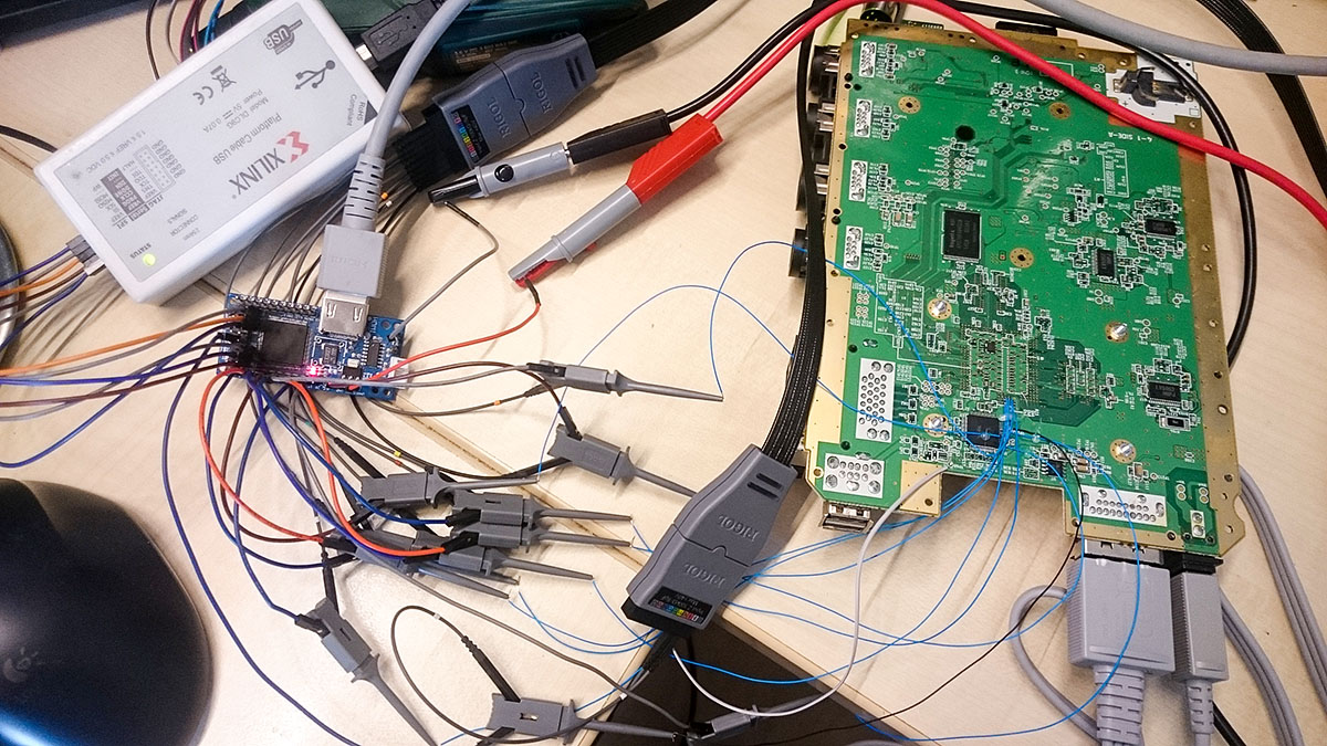
Note that using such a setup is not recommended. The signal integrity sucks, to get a stable and flickering-pixel-freei image I had to hold up the 54MHz wire to keep it separated from the other wires and even then I couldn't get a stable 480p image.
But it was enough to capture this over HDMI:
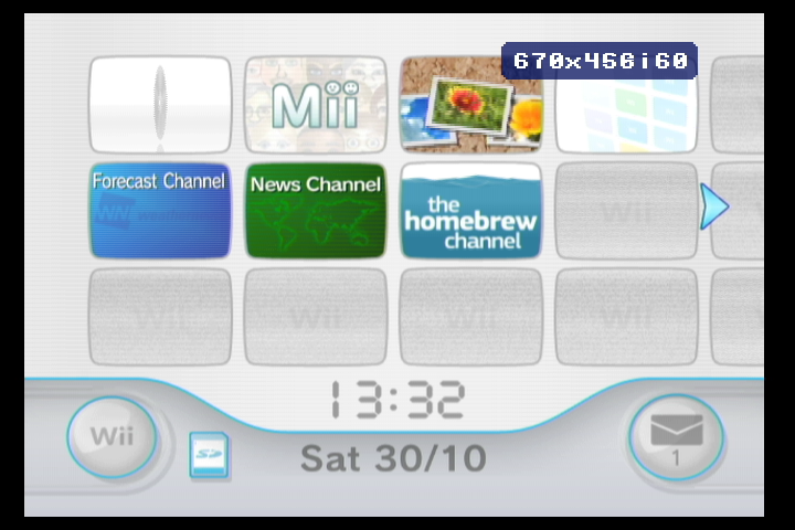
So, the theory that the internal video bus of the Wii uses the same signals as the Gamecube is true - which means that GCVideo can use it. However, the Wii's bus uses 1.8V levels, which is barely enough to register as a "1" on an input that is meant for 3.3V signals. Fortunately, this is not a big issue - the FPGAs used for GCVideo can be configured to accept 1.8V signals on their inputs - but this requires a different bit stream. I'll probably upload the files for that soon.
To connect a GCVideo board to the Wii, you need a few pins from the AVE-RVL video encoder:
I haven't actually tested the audio signals yet, the pin numbers may be wrong!
Power (5V/GND) can be taken from one of the USB connectors. I haven't traced out the Gamecube controller inputs yet to find a good spot to connect to - a direct connection to the pad's data line on the connector is possible, but not recommended. (Edit: See below) A suitable point for connecting the CableDetect signal is also not known yet, but simply plugging in a component cable is enough to enable 480p - or you could
CableDetect - unkown, just plug in a component cable for now or connect pins 8 and 10 on the AV connector.
Next problem: Figuring out the mechanical issues of either integrating a board into the Wii or routing a (short!) cable with all signals out of the case.
Edit: The circuit for the controller data lines is a bit simpler in the Wii than in the Gamecube, but there is at least a little bit of protection on the data lines. On the RVL-CPU-60 board I used, there are four test points near the four Gamecube controller connectors, labelled TP 27 to 30. Connecting the PadData line from GCVideo to one of them should work - I can't test it easily right now. For Wiis without Gamecube ports I'll need to implement a different solution for controlling the OSD.
Note that using such a setup is not recommended. The signal integrity sucks, to get a stable and flickering-pixel-freei image I had to hold up the 54MHz wire to keep it separated from the other wires and even then I couldn't get a stable 480p image.
But it was enough to capture this over HDMI:
So, the theory that the internal video bus of the Wii uses the same signals as the Gamecube is true - which means that GCVideo can use it. However, the Wii's bus uses 1.8V levels, which is barely enough to register as a "1" on an input that is meant for 3.3V signals. Fortunately, this is not a big issue - the FPGAs used for GCVideo can be configured to accept 1.8V signals on their inputs - but this requires a different bit stream. I'll probably upload the files for that soon.
To connect a GCVideo board to the Wii, you need a few pins from the AVE-RVL video encoder:
Code: Select all
64 - VData 0
 1 - VData 1
 2 - VData 2
 3 - VData 3
 6 - VData 4
 7 - VData 5
 8 - 54MHz (or TP232 next to the chip)
11 - CSel
13 - VData 6
14 - VData 7
25 - I2S_BClock  (unverified)
27 - I2S_LRClock  (unverified)
29 - I2S_Data  (unverified)
Power (5V/GND) can be taken from one of the USB connectors. I haven't traced out the Gamecube controller inputs yet to find a good spot to connect to - a direct connection to the pad's data line on the connector is possible, but not recommended. (Edit: See below) A suitable point for connecting the CableDetect signal is also not known yet, but simply plugging in a component cable is enough to enable 480p - or you could
CableDetect - unkown, just plug in a component cable for now or connect pins 8 and 10 on the AV connector.
Next problem: Figuring out the mechanical issues of either integrating a board into the Wii or routing a (short!) cable with all signals out of the case.
Edit: The circuit for the controller data lines is a bit simpler in the Wii than in the Gamecube, but there is at least a little bit of protection on the data lines. On the RVL-CPU-60 board I used, there are four test points near the four Gamecube controller connectors, labelled TP 27 to 30. Connecting the PadData line from GCVideo to one of them should work - I can't test it easily right now. For Wiis without Gamecube ports I'll need to implement a different solution for controlling the OSD.
- Attachments
-
- wiimenu.png
- (228.86 KiB) Not downloaded yet
-
- setup.jpg
- (292.91 KiB) Not downloaded yet
Last edited by Unseen on Sun May 08, 2016 6:20 pm, edited 1 time in total.
Asking for support by PM is anti-social. Ask in an open forum instead, so other people can benefit from the answers!
Re: Cloning the GameCube component cable
Our savior returns  . Quite the dedication there, amazing work; GCvideo is quickly becoming the standard to HDMI-mod post SNES nintendo consoles
On another note, would it be possible for games that use the 640x480 rendering buffer such as smash melee, to display without black borders? If I am correct the signal is the NTSC video standard of 720x480, so there are 720-640=80 pixels added by the cubes output image and are flagged as active? Would it be possible for GCvideo to flag those pixels as non-active, so my TV doesnt treat them as part of the image and upscales without black borders? Or am I talking out of my ass here?
On another note, would it be possible for games that use the 640x480 rendering buffer such as smash melee, to display without black borders? If I am correct the signal is the NTSC video standard of 720x480, so there are 720-640=80 pixels added by the cubes output image and are flagged as active? Would it be possible for GCvideo to flag those pixels as non-active, so my TV doesnt treat them as part of the image and upscales without black borders? Or am I talking out of my ass here?
Last edited by tesla246 on Sun May 08, 2016 5:56 pm, edited 1 time in total.
Dream mod: HI-speed port device utilizing 4:4:4 RGB 32 bit colour, 720p video and variable refresh rate.
Favourite mod: GC Loader flashed with latest swiss.
Eagerly awaiting a normal, form-factor wise, wireless controller with rumble.
Favourite mod: GC Loader flashed with latest swiss.
Eagerly awaiting a normal, form-factor wise, wireless controller with rumble.
Re: Cloning the GameCube component cable
It is basically possible, although I'm not sure if it would still fit in the (tiny) amount of space that is left in the FPGA. This would of course result in a slight horizontal stretching of the picture.tesla246 wrote:Would it be possible for GCvideo to flag those pixels as non-active, so my TV doesnt treat them as part of the image and upscales without black borders? Or am I talking out of my ass here? :D
Asking for support by PM is anti-social. Ask in an open forum instead, so other people can benefit from the answers!
Re: Cloning the GameCube component cable
Ah ok, fair enough. But wouldn't it result in a slightly more accurately scaled image (both height and width times 2.25, in 4:3 tv mode, would scale perfect in future 8k tv's)? If the fov is 16:9, or slightly altered because of gamecube pixels not being square, it shouldn't appear stretched when selecting wide mode on the tv, correct?
Last edited by tesla246 on Mon May 09, 2016 1:09 pm, edited 1 time in total.
Dream mod: HI-speed port device utilizing 4:4:4 RGB 32 bit colour, 720p video and variable refresh rate.
Favourite mod: GC Loader flashed with latest swiss.
Eagerly awaiting a normal, form-factor wise, wireless controller with rumble.
Favourite mod: GC Loader flashed with latest swiss.
Eagerly awaiting a normal, form-factor wise, wireless controller with rumble.
-
ShockSlayer
- Posts: 97
- Joined: Sat Feb 05, 2011 7:21 pm
Re: Cloning the GameCube component cable
If you're looking for alternate points on the Wii for 5v, controllers, and cabledetect(listed as "mode"), I've mapped out a few here: http://bitbuilt.net/forums/index.php?th ... #post-1492
Pin 8's the actual Cabledetect(in most pinouts online they're both listed as "mode,") pin 10 is just 3.3v, so you can grab that from anywhere. The easiest point happens to be quite close, and is also marked.
Hope that helps. Nice work on this, can't wait to see the code posted! send it to mega pls
Pin 8's the actual Cabledetect(in most pinouts online they're both listed as "mode,") pin 10 is just 3.3v, so you can grab that from anywhere. The easiest point happens to be quite close, and is also marked.
Hope that helps. Nice work on this, can't wait to see the code posted! send it to mega pls

Re: Cloning the GameCube component cable
Interesting, that means the pinout I found is incorrect - it claimed that pin 8 had to be grounded and suggested pin 10 as the closest source. If it's really just a 3.3V input like on the Gamecube, the CableDetect pin from the FPGA could be connected to it directly. I'll have to make a small change to the code to make sure the FPGA never outputs 0V on that pin, otherwise setting "Enable 480p" to "No" in the OSD and plugging in a component cable would result in a problematic situation.ShockSlayer wrote:Pin 8's the actual Cabledetect(in most pinouts online they're both listed as "mode,") pin 10 is just 3.3v, so you can grab that from anywhere.
Do you happen to know if that pin has a pulldown resistor connected to it?
I'll let you into a secret: The code is currently the same that is in my Github repo, I just changed a few lines in the UCF file and compiled it.Nice work on this, can't wait to see the code posted! send it to mega pls
Edit: Random idea of the moment - does anyone know if it would be feasible to take a standard flat flex cable (0.5mm pitch) and solder one end to the pins of the AVE? Almost all signals are on a single side of the chip and the remaining ones could be wired to the cable manually. It could then be folded once and leave the case below the standard AV connector - one of the four heat sink screws would have to be left out though.
Asking for support by PM is anti-social. Ask in an open forum instead, so other people can benefit from the answers!
-
ShockSlayer
- Posts: 97
- Joined: Sat Feb 05, 2011 7:21 pm
Re: Cloning the GameCube component cable
No resistors, just a component marked D2 connecting it to ground:

It probably serves the same purpose. But aside from that, it's a straight connection from the plug to the final via.
It probably serves the same purpose. But aside from that, it's a straight connection from the plug to the final via.
Re: Cloning the GameCube component cable
Are you guys sure the cube/wii doesn't have two cable detect lines? From the software side there are two individual bits (in the same hw register) that are checked, one indicates the presence of a component cable and the other is used to detect a japanese console i.e. D-terminal cable.
Re: Cloning the GameCube component cable
On the Gamecube, there is only a single pin on the digital AV port that is an input. Maybe the second bit is just a hard-wired region bit?tueidj wrote:Are you guys sure the cube/wii doesn't have two cable detect lines? From the software side there are two individual bits (in the same hw register) that are checked, one indicates the presence of a component cable and the other is used to detect a japanese console i.e. D-terminal cable.
Asking for support by PM is anti-social. Ask in an open forum instead, so other people can benefit from the answers!