Page 1 of 1
WKF to GC wiring help
Posted: Sun Feb 16, 2014 1:48 pm
by iamdablasta
I am not entirely sure how I should wire the WKF.
The picture should explain my question, but I am retarded at explaining things, so maybe not.
Re: WKF to GC wiring help
Posted: Sun Feb 16, 2014 3:34 pm
by megalomaniac
1 = 28
Re: WKF to GC wiring help
Posted: Sun Feb 16, 2014 3:41 pm
by iamdablasta
megalomaniac wrote:1 = 28
So 1 on the breakout board goes to 28 on the mobo?
Or 1 on the mobo goes to 28 on the breakout board
Don't wanna make any mistakes as the shop I bought it from is out on WKF's and importing is SO expensive (like 50$ minimum it seems :L
If I ever happen to put the FFC ribbon in the wrong way, will it fry? Or just not work till I put it in the right way?
Re: WKF to GC wiring help
Posted: Sun Feb 16, 2014 3:47 pm
by megalomaniac
This can get really confusing really fast
Maybe I should ask this first...
Which pin/solder hole on that breakout board do you think is #1
Re: WKF to GC wiring help
Posted: Sun Feb 16, 2014 3:56 pm
by iamdablasta
megalomaniac wrote:This can get really confusing really fast
Maybe I should ask this first...
Which pin/solder hole on that breakout board do you think is #1
Ah, I don't actually use that breakout board.
The one I have is numbered from 1 to 60 on every pin, so I won't have issues with that.
http://www.seeedstudio.com/depot/lcd-ex ... p-200.html
Re: WKF to GC wiring help
Posted: Wed Feb 19, 2014 10:50 pm
by iamdablasta
Not really sure how often you bump in this forum, but here goes.
Re: WKF to GC wiring help
Posted: Wed Feb 19, 2014 11:49 pm
by novenary
Both the diagram and the table are equivalent. The numbers on the diagram are the pin numbers on the breakout side that you should connect the GC pins to. Oh and it's viewed from the top of the motherboard.
Re: WKF to GC wiring help
Posted: Wed Feb 19, 2014 11:54 pm
by iamdablasta
Streetwalker wrote:Both the diagram and the table are equivalent. The numbers on the diagram are the pin numbers on the breakout side that you should connect the GC pins to.
You know what? That actually makes perfect sense.
Thanks for explaining it just the way for me to understand :)
While I am not stupid, I am not always the brightest haha.
 WKF, here I come!
Re: WKF to GC wiring help
Posted: Wed Feb 19, 2014 11:57 pm
by novenary
LOL glad I helped anyway.

Re: WKF to GC wiring help
Posted: Thu Feb 20, 2014 12:26 am
by iamdablasta
One final question, merely just in case, does the 3.3v pin (32) go directly to the 3.3v source as shown in picture attachment? (And is the reference correct? I would HATE to accidentally kill my WKF)
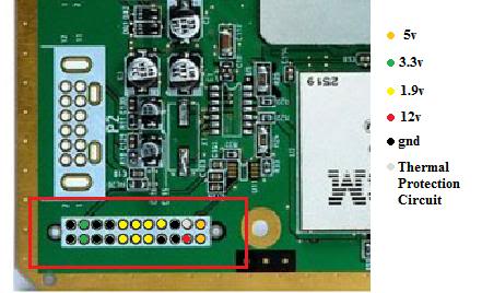
- GCPower.jpg
- Power sources on gc mobo
- (26.5 KiB) Not downloaded yet
Sorry about all the precaution, and thank you everyone for being so patient with eachother here in this forum.
Re: WKF to GC wiring help
Posted: Thu Feb 20, 2014 12:30 am
by novenary
Yes it does.
Edit : To clarify, this is clean regulated power from the regulator board on this connector so should you need any power you must grab it from here unless you are soldering to another connector with the proper voltage.
Re: WKF to GC wiring help
Posted: Thu Feb 20, 2014 12:58 am
by iamdablasta
All set, once the breakout board (I gave up on soldering directly to the FFC cable, impossible) and a replacement ribbon arrives.
Thanks once again, huge help. +1
I'll update when parts come, but I think we can already conclude it will work as my soldering skills are functional and I've gone through pretty much everything there is hardware wise.
Re: WKF to GC wiring help
Posted: Thu Feb 20, 2014 2:08 am
by kinect360
I had mine wired directly to 3.3v as shown in the picture, there is no need for this as it creates a mess of wires. Simply attach it to the 3.3v line in mem slot B. Much closer, shorter wire and cleaner look

My wasp fusion is wired like this and the memcard slot and wasp work fine. You can look at the sd gecko sticky to get the pinouts for memcard slots.
Re: WKF to GC wiring help
Posted: Thu Feb 20, 2014 6:34 am
by novenary
Yeah but the memory card port gets in the way since it's on top of the mobo. You can run the 3.3v wire from the regulator under the heat sink between the CPU and GPU or even better between GPU and ARAM. Use pics for reference or temporarily remove the heatsink although I don't recommend doing that.
Re: WKF to GC wiring help
Posted: Thu Feb 20, 2014 11:25 am
by kinect360
Removing memory card port B is almost always a must for a portable. So without the memory card port there, there is no issue.
Re: WKF to GC wiring help
Posted: Thu Feb 20, 2014 12:46 pm
by novenary
Yeah but I don't think he's making a portable here.
Re: WKF to GC wiring help
Posted: Thu Feb 20, 2014 2:19 pm
by iamdablasta
No portable, maybe one day. At least a few years minimum.
Re: WKF to GC wiring help
Posted: Thu Feb 20, 2014 2:33 pm
by kinect360
Ah okay my bad, you can still take 3,3v from under the memory card port
Re: WKF to GC wiring help
Posted: Thu Feb 20, 2014 3:07 pm
by iamdablasta
kinect360 wrote:Ah okay my bad, you can still take 3,3v from under the memory card port :)
I am considering it, but I think I'll start with the first plan.
I do plan to add internal memorycards and such (less bulky cube, and less loose parts to drag along to buddies), so I might just solder it there when I do the memory cards internal, but I haven't planned doing it immediately. a 128mb card (1024block) memory card should probably do just the job.