Hello,
Looking for a schematic on this, The one on this board is gone, and a few links point to other boards and a video but the boards show nothing of any help, and the video you can't see what is going on. The best i can figure out is use a 10k res and a B547 transistor for the analog side. Leave the digital side alone stack the switches on top of each other and that is it. But it would be nice to have a schematic or a couple pics of how it is all setup and configure when complete inside a control etc.
Thanks
analog and digital trigger buttons
Re: analog and digital trigger buttons
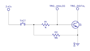
You can do both the Analog and Digital of the Trigger with just 1 Tact switch, 2 Resistors and an NPN Transistor like the 3904.
The Trigger button is common ground, so it goes Lo to activate, but the Trigger Analog is Lo at rest and goes Hi to fully activate.
If you use a single Tact switch connected to the 3.43v rail to drive the Trigger Analog line Hi, that can also activate the NPN to drive the Trigger Digital button line Lo.
Install a 10k Pull Down on the Trigger's Analog line, to keep it Lo, as floating Analog lines can and will do all manner of weirdo things. The 1k is recommended so you don't frag the Transistor Base and it also makes a voltage divider for the Analog line, giving around 3v to the Trigger Analog line when the Tact is pressed, which is more how the Trigger Slide works when fully pulled as it's just a Variable Resistor.
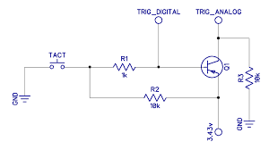
If you wish to keep all of your buttons common ground, you can flip all of that and use the 3906 instead, but you'll need an additional 10k on the Trigger Analog line to keep it pulled Lo then.
The Trigger button is common ground, so it goes Lo to activate, but the Trigger Analog is Lo at rest and goes Hi to fully activate.
If you use a single Tact switch connected to the 3.43v rail to drive the Trigger Analog line Hi, that can also activate the NPN to drive the Trigger Digital button line Lo.
Install a 10k Pull Down on the Trigger's Analog line, to keep it Lo, as floating Analog lines can and will do all manner of weirdo things. The 1k is recommended so you don't frag the Transistor Base and it also makes a voltage divider for the Analog line, giving around 3v to the Trigger Analog line when the Tact is pressed, which is more how the Trigger Slide works when fully pulled as it's just a Variable Resistor.
If you wish to keep all of your buttons common ground, you can flip all of that and use the 3906 instead, but you'll need an additional 10k on the Trigger Analog line to keep it pulled Lo then.
- Attachments
-
- trigger2.png
- (3.27 KiB) Not downloaded yet
-
- trigger1.png
- (3.04 KiB) Not downloaded yet
Screwing up is one of the best learning tools, so long as the only thing you're not learning is how to screw up.
Re: analog and digital trigger buttons
Great, thanks now I see what I have to do.
Re: analog and digital trigger buttons
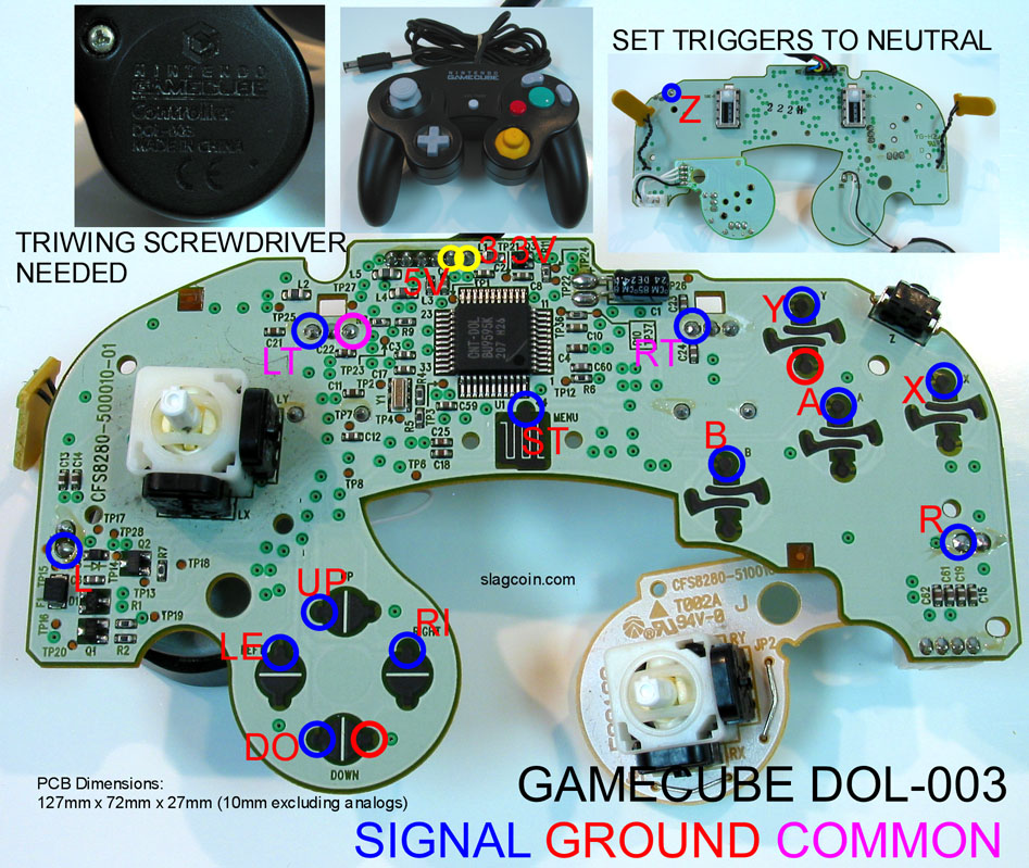
One more question, What pin is what on the Analog side, I see 3 pins middle pin Neg other 2 pins lead to caps. does it matter what one is used?
As I was. I found a picture giving what I needed.
As I was. I found a picture giving what I needed.
- Attachments
-
- Wjl7D3F.jpg
- (227.37 KiB) Not downloaded yet
Re: analog and digital trigger buttons
1 2 3
1 - Trigger Analog
2 - Ground
3 - 3.43v
1 - Trigger Analog
2 - Ground
3 - 3.43v
Screwing up is one of the best learning tools, so long as the only thing you're not learning is how to screw up.