Difference between revisions of "Xeno Fusion"

From GC-Forever Wiki
Jump to navigation Jump to search
(added youtube link)
 
(7 intermediate revisions by the same user not shown)
Line 10: Line 10:
 
'''concept:''' use a xenogc modchip in tandem with wiikey fusion drive replacement <br>
 
'''concept:''' use a xenogc modchip in tandem with wiikey fusion drive replacement <br>
 
'''theory:''' use the atmega 8 on the xenogc modchip to trigger a response required for the WKF to initialize iso loading.<br>
 
'''theory:''' use the atmega 8 on the xenogc modchip to trigger a response required for the WKF to initialize iso loading.<br>
'''proof of concept:''' haha, no proof to show yet, but initial testing promises good results
+
'''proof of concept:''' http://www.youtube.com/watch?v=L-7U0fu-z3o <br>  
 
 
==Technical Data==
 
The foundation for Xeno Fusion is based upon basic LED connectivity.<br>
 
The diagram in figure 1 shows an LED connected to an Atmega8 (XenoGC) at pin PD5 and GND. Current flows from the anode to the cathode and a resistor is used for current limiting protection. Atmega provides up to 40mA output per pin. <br>


'''fig. 1'''<br>
 
[[File:Xeno_fusion_example_LED.png‎‎|500px]]<br>
 
Atmega8L (XenoGC) operates at 3.3v. <br>
 
If an LED is rated at 2.0v forward voltage with up to 20mA forward current, then a current-limiting resistor value of 220ohms will provide 5.9mA of operational current which is under the 20mA of forward current allowing safe operation of the LED. Also the current-limiting resistor creates a 1.3v voltage drop. <br><br>
 
current = (( supply voltage - forward voltage ) / resistor value ) * 1000  <br>
 
current = (( 3.3v - 2v ) / 220 ohm) * 1000 <br>
 
current = (( 1.3v ) / 220ohm) * 1000 <br>
 
current = (( 0.0059 ) * 1000 <br>
 
current = 5.9 mA <br>


voltage drop = resistance * current<br>
 
voltage drop = 220ohm * 5.9 mA <br>
 
voltage drop = ~ 1.3v<br>


==Circuit==


add diagram and parts here


==Glossary==


{| border="3" style="margin-left: 3em;"
 
|-
 
! colspan="2" style="background:lightblue;font-size:10pt" width="900"| Confusing terms easily explained
 
|-
 
! scope="col" width = "200" |  Reverse Voltage
 
|  maximum voltage that can be applied before it blows up
 
|-
 
! scope="row" | Forward Voltage
 
|  minimum voltage required to operate. <br>(basically, it is safe to apply any voltage amount between "forward" and "reverse" )
 
|-
 
! scope="row" | Maximum (or Continuous)<br> Forward Current
 
|  maximum current that can be continuously applied to a device before it burns up
 
|-
 
! scope="row" | Operational Current
 
|  any amount of current provided to a device which allows save operation<br> (see Forward Current)
 
|-
 
! scope="row" | Current-Limiting Resistor
 
|  a resistor used to protect a device from receiving too much current <br> (see Forward Current)
 
|-
 
! scope="row" | Max Peak Forward Current
 
|  maximum current that can be applied during a brief current spike. <br> typically ignore this value and rely on the forward current the device can safely handle to determine the current limiting resistor value.
 
|-
 
! scope="row" | Voltage Drop
 
|  the voltage difference from the power source subtracted by the forward voltage equals the voltage used by the current limiting resistor.
 
|-
 
! scope="row" | Transistor
 
|  used to amplify and switch electronic signals and electrical power. <br> (two types of bipolar transistors: NPN or PNP)
 
|-
 
! scope="row" | Relay
 
|  electromechanical or solid state device used to provide a normally open or normally closed output when energized or de-energized
 
|-
 
! scope="row" | Diode
 
|  device which allows current to pass in one direction and blocks current in the opposite direction
 
|-
 
! scope="row" | Photodiode
 
|  device capable of converting light into either current or voltage <br> (a solar cell is a photodiode)
 
|-
 
! scope="row" | Infrared LED
 
|  LED which outputs light in the infrared spectrum <br> (see photodiode)
 
|-
 
! scope="row" | ADC
 
| Analog to Digital Converter which can be used to measure voltage
 
|}


 +
[[File:XenoFUSION pinout.png‎‎|200px]] [[File:WKF slot voltage.png|200px]]<br>


Latest revision as of 23:36, 27 March 2013

....this page is under destruction


Xeno fusion.png

Main

concept: use a xenogc modchip in tandem with wiikey fusion drive replacement
theory: use the atmega 8 on the xenogc modchip to trigger a response required for the WKF to initialize iso loading.
proof of concept: http://www.youtube.com/watch?v=L-7U0fu-z3o
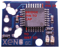
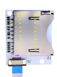

XenoFUSION pinout.png WKF slot voltage.png