Difference between revisions of "Xeno Fusion"
Megalomaniac (talk | contribs) |
Megalomaniac (talk | contribs) |
||
| Line 13: | Line 13: | ||
| − | '''if anyone is seeing this, ignore EVERYTHING below....i need to figure out if i still want to use this data....''' | + | the data below was gonna be an attempt to explain how to use a solid state relay which consists of an infrared led and a photodiode...<br>the main reason to use this component was to provide electrical isolation / protection...but i guess if you think about, whats the point of electrical isolation when the xeno and wiikey are all tied together anyways...<br> All this data will be removed, and new project direction will be presented..<br> |
| + | |||
| + | '''if anyone is seeing this, ignore EVERYTHING below....i need to figure out if i still want to use this data....'''<br> | ||
| + | |||
---- | ---- | ||
Revision as of 10:22, 27 March 2013
....this page is under destruction

|
|---|
Main
concept: use a xenogc modchip in tandem with wiikey fusion drive replacement
theory: use the atmega 8 on the xenogc modchip to trigger a response required for the WKF to initialize iso loading.
proof of concept: haha, no proof to show yet, but initial testing promises good results
the data below was gonna be an attempt to explain how to use a solid state relay which consists of an infrared led and a photodiode...
the main reason to use this component was to provide electrical isolation / protection...but i guess if you think about, whats the point of electrical isolation when the xeno and wiikey are all tied together anyways...
All this data will be removed, and new project direction will be presented..
if anyone is seeing this, ignore EVERYTHING below....i need to figure out if i still want to use this data....
Technical Data
The foundation for Xeno Fusion is based upon basic LED connectivity.
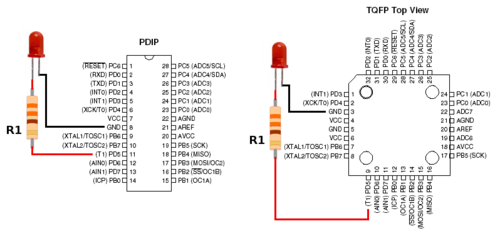
The diagram in figure 1 shows an LED connected to an Atmega8 (XenoGC) at pin PD5 and GND. Current flows from the anode to the cathode and a resistor is used for current limiting protection.
fig. 1

Atmega8L (XenoGC) operates at 3.3v and will deliver up to 3.3v @ 40mA output per pin.
If an LED is rated at 2.0v forward voltage with up to 20mA forward current, then a current-limiting resistor value of 220ohms will provide 5.9mA of operational current which is under 20mA of forward current allowing a safe operation condition for the LED. Also the current-limiting resistor creates a 1.3v voltage drop.
current = (( supply voltage - forward voltage ) / resistor value ) * 1000
current = (( 3.3v - 2v ) / 220 ohm) * 1000
current = (( 1.3v ) / 220ohm) * 1000
current = (( 0.0059 ) * 1000
current = 5.9 mA
voltage drop = resistance * current
voltage drop = 220ohm * 5.9 mA
voltage drop = ~ 1.3v
blah blah blah
other notes just for now:
both xeno leds have 100ohm resistors
xeno red led voltage across diode = 1.74v
15.6mA = ((3.3v - 1.74v) / 100ohm) * 1000
xeno yellow led voltage across diode = 1.85v
14.5mA = ((3.3v - 1.74v) / 100ohm) * 1000
total current draw = 30.1mA
Circuit
add diagram and parts here
Glossary
| Confusing terms easily explained | |
|---|---|
| Reverse Voltage | maximum voltage that can be applied to a component before it blows up |
| Forward Voltage | minimum voltage required by a component for normal operation. (basically, it is safe to apply any voltage amount between "forward" and "reverse" ) |
| Maximum (or Continuous) Forward Current |
maximum current that can be continuously applied to a component before it burns up |
| Operational Current | any amount of current provided to a component which allows save operation (see Forward Current) |
| Current-Limiting Resistor | a resistor used to protect a component from receiving too much current (see Forward Current) |
| Max Peak Forward Current | maximum current that can be applied during a brief current spike. typically ignore this value and rely on the forward current the component can safely handle to determine the current limiting resistor value. |
| Voltage Drop | the voltage difference from the power source subtracted by the forward voltage equals the voltage used by the current limiting resistor. |
| Transistor | component used to amplify and switch electronic signals and electrical power. (two types of bipolar transistors: NPN or PNP) |
| Relay | electromechanical or solid state device used to provide a normally open or normally closed output when energized or de-energized |
| Diode | component which allows current to pass in one direction and blocks current in the opposite direction |
| Infrared LED | Light Emitting Diode which outputs light in the infrared spectrum |
| optical isolator | component that transfers electrical signals between two isolated circuits by using light (see Infrared LED) |
| Photodiode | component capable of converting light into either current or voltage (example: a solar cell is a photodiode) |
| Photodiode opto-isolator | a device which consists of a photodiode paired with an LED. The LED provides a source of light, the photodiode detects the light and allows the flow of energy from an external source. non-mechanical equivalent of a relay. (see Relay) |
| ADC | Analog to Digital Converter which can be used to measure voltage |