Shuriken Video
Re: Shuriken Video
due to timing analysis, maximum frequency of 0.2 version can reach to 83.6 Mhz, but 0.5 is only 54.2 Mhz, I think 54.2 Mhz is a critical condition for stable
Wild Scientist
-
happy_bunny
- Posts: 106
- Joined: Mon Mar 09, 2015 10:57 pm
Re: Shuriken Video
Can you explain more dont understand is 0.5 also bad on your setup.
Re: Shuriken Video
Oh, I fixed the problem, first is edit ucf file under planahead, give TS_CLOCK_54 more strict constraint, for example, 70Mhz, this give me more stable synthesize result.happy_bunny wrote:Can you explain more dont understand is 0.5 also bad on your setup.
then I measure the 1.2v LDO input and output using oscillsocope, I find that thay are noisy, so I add three tantalum-caps, look like this:


now 0.5 version works very nice.
Wild Scientist
Re: Shuriken Video
Wild Scientist
-
happy_bunny
- Posts: 106
- Joined: Mon Mar 09, 2015 10:57 pm
Re: Shuriken Video
thank you for looking into this for me you are a star 
which value did you use for the tantalum-caps ? can you copy paste (upload) the ucf changes please. Also did you keep the buffering in the gcdv_decode.vhd file ?
thanks again dude
which value did you use for the tantalum-caps ? can you copy paste (upload) the ucf changes please. Also did you keep the buffering in the gcdv_decode.vhd file ?
thanks again dude
Re: Shuriken Video
@happy_bunny:
the tantalum-caps are all 20V 1uF,
ucf change: TIMESPEC TS_CLOCK_54 = PERIOD "CLOCK_54" 70 MHz HIGH 50 %;
and the last,
the buffering in the gcdv_decode.vhd is hardly fit into the FPGA, so I can't keep them.
the tantalum-caps are all 20V 1uF,
ucf change: TIMESPEC TS_CLOCK_54 = PERIOD "CLOCK_54" 70 MHz HIGH 50 %;
and the last,
the buffering in the gcdv_decode.vhd is hardly fit into the FPGA, so I can't keep them.
Wild Scientist
-
happy_bunny
- Posts: 106
- Joined: Mon Mar 09, 2015 10:57 pm
Re: Shuriken Video
"The 1.2 vreg is the same as the pluto board but the input and ouput caps are different maybe they need to be beefed up."
This is incorrect I have had time to check and the pluto board uses a AMS1117 (well the one I have does)
http://www.advanced-monolithic.com/pdf/ds1117.pdf
This has a max current output of 1.5A, currently on the board I created it has a MCP1826
http://www.farnell.com/datasheets/1769092.pdf
This has a max current output of 1A.
@HyperIris
Datasheet states 4.7uF input cap and 1uF output cap, so I would suggest changing the input cap to 4.7uF.
@andre104623 and any else with a SPDIF connector.
I think filling up the fgpa made my board draw double the current and then on top of that connecting the SPDIF connector resulted in the 1.2reg dropping below 1.2volts which I think then caused the fpga to run hot hopefully the 1.2vreg gave up in the end before the fpga got damaged.
I would recommend disconnecting SPDIF connect or upgrading your 1.2 vreg for this one MCP1827 (farnell no 1852008) 1.5A
http://www.farnell.com/datasheets/456104.pdf
Also upgrade the input / output caps to 4.7uF and 1uF that will help make your vreg stable at the higher currents, will update my website later with this info.
This is incorrect I have had time to check and the pluto board uses a AMS1117 (well the one I have does)
http://www.advanced-monolithic.com/pdf/ds1117.pdf
This has a max current output of 1.5A, currently on the board I created it has a MCP1826
http://www.farnell.com/datasheets/1769092.pdf
This has a max current output of 1A.
@HyperIris
Datasheet states 4.7uF input cap and 1uF output cap, so I would suggest changing the input cap to 4.7uF.
@andre104623 and any else with a SPDIF connector.
I think filling up the fgpa made my board draw double the current and then on top of that connecting the SPDIF connector resulted in the 1.2reg dropping below 1.2volts which I think then caused the fpga to run hot
I would recommend disconnecting SPDIF connect or upgrading your 1.2 vreg for this one MCP1827 (farnell no 1852008) 1.5A
http://www.farnell.com/datasheets/456104.pdf
Also upgrade the input / output caps to 4.7uF and 1uF that will help make your vreg stable at the higher currents, will update my website later with this info.
-
andre104623
- Posts: 694
- Joined: Wed May 07, 2014 2:24 pm
Re: Shuriken Video
I have since replaced all caps, resistors, and regs then tryed flashing the 0.2 update and 0.5 but no luck. One thing i did noticed is if i try to get a read back from the FPGA in impact it will fail. The SPI has been changed as well usually the bitsteam would load the FPGA config from SPI flash which is fine I can flash the SPI but if the read back is failing i would guess the FPGA is fried. Maybe it was the SPDIF or the TV i was using back feeding 5v then that could of done it I'm not really sure but the SPDIF was powered by the power rail of the cube so i really dont think that was the reason
Re: Shuriken Video
you mean that you connected the FPGA spdif pin DIRECT to something like 5V TTL cricuit without any protect?andre104623 wrote:I have since replaced all caps, resistors, and regs then tryed flashing the 0.2 update and 0.5 but no luck. One thing i did noticed is if i try to get a read back from the FPGA in impact it will fail. The SPI has been changed as well usually the bitsteam would load the FPGA config from SPI flash which is fine I can flash the SPI but if the read back is failing i would guess the FPGA is fried. Maybe it was the SPDIF or the TV i was using back feeding 5v then that could of done it I'm not really sure but the SPDIF was powered by the power rail of the cube so i really dont think that was the reason
Wild Scientist
-
andre104623
- Posts: 694
- Joined: Wed May 07, 2014 2:24 pm
Re: Shuriken Video
No i used a 3.3 volt lite-on optical transmitter same one approved for the pluto 2x hdmiHyperIris wrote:you mean that you connected the FPGA spdif pin DIRECT to something like 5V TTL cricuit without any protect?andre104623 wrote:I have since replaced all caps, resistors, and regs then tryed flashing the 0.2 update and 0.5 but no luck. One thing i did noticed is if i try to get a read back from the FPGA in impact it will fail. The SPI has been changed as well usually the bitsteam would load the FPGA config from SPI flash which is fine I can flash the SPI but if the read back is failing i would guess the FPGA is fried. Maybe it was the SPDIF or the TV i was using back feeding 5v then that could of done it I'm not really sure but the SPDIF was powered by the power rail of the cube so i really dont think that was the reason
Re: Shuriken Video
do you append a driver transistor to drive the transmitter? I guess that use FPGA drive transmitter directly will makes FPGA over current and burned.andre104623 wrote:No i used a 3.3 volt lite-on optical transmitter same one approved for the pluto 2x hdmiHyperIris wrote:you mean that you connected the FPGA spdif pin DIRECT to something like 5V TTL cricuit without any protect?andre104623 wrote:I have since replaced all caps, resistors, and regs then tryed flashing the 0.2 update and 0.5 but no luck. One thing i did noticed is if i try to get a read back from the FPGA in impact it will fail. The SPI has been changed as well usually the bitsteam would load the FPGA config from SPI flash which is fine I can flash the SPI but if the read back is failing i would guess the FPGA is fried. Maybe it was the SPDIF or the TV i was using back feeding 5v then that could of done it I'm not really sure but the SPDIF was powered by the power rail of the cube so i really dont think that was the reason
Wild Scientist
-
megalomaniac

- Posts: 2480
- Joined: Sun Aug 21, 2011 5:33 am
- Location: Drunk in Texas
- Contact:
Re: Shuriken Video
why do you need a transistor?
the signal is connected to an optical transmitter...what is there that would cause any potential to drive the current over limits?
within the optical connector the signal is tied to an LED....the LED is a diode...the optical receiver only receives optical data, it does not transmit...the optical transmitter is powered by 3v source for the LED...
this basic design and functionality allows the FPGA and any other equipment to be electrically isolated from other components (aka audio system)
>>> BadAssConsoles.com <<<emu_kidid wrote: beer is like WD40 for megalomaniac's brain, gets the gears moving
Re: Shuriken Video
I don't know the part No. of the transmitter, of cause, in theory, it's just a LED, but I can't sure it has a resistor inside. if FPGA 3.3v IO direct connect to LED, it will burn LED or IO pin itself.megalomaniac wrote:why do you need a transistor?
the signal is connected to an optical transmitter...what is there that would cause any potential to drive the current over limits?
within the optical connector the signal is tied to an LED....the LED is a diode...the optical receiver only receives optical data, it does not transmit...the optical transmitter is powered by 3v source for the LED...
this basic design and functionality allows the FPGA and any other equipment to be electrically isolated from other components (aka audio system)
LED is current driven device, not voltage driven.
Wild Scientist

Re: Shuriken Video
The SPDIF transmitter is not just a LED, it includes a driver circuit and the input is a TTL-compatible logic signal. See the datasheet here.HyperIris wrote:I don't know the part No. of the transmitter, of cause, in theory, it's just a LED, but I can't sure it has a resistor inside. if FPGA 3.3v IO direct connect to LED, it will burn LED or IO pin itself.
LED is current driven device, not voltage driven.
Asking for support by PM is anti-social. Ask in an open forum instead, so other people can benefit from the answers!
Re: Shuriken Video
got, that, so this type of transmitter is safe for use.Unseen wrote:The SPDIF transmitter is not just a LED, it includes a driver circuit and the input is a TTL-compatible logic signal. See the datasheet here.HyperIris wrote:I don't know the part No. of the transmitter, of cause, in theory, it's just a LED, but I can't sure it has a resistor inside. if FPGA 3.3v IO direct connect to LED, it will burn LED or IO pin itself.
LED is current driven device, not voltage driven.
Wild Scientist
-
happy_bunny
- Posts: 106
- Joined: Mon Mar 09, 2015 10:57 pm
Re: Shuriken Video
oh Current Consumption IDD of only 8mA, and its being driven of the cubes supply rail this is a puzzle very odd. So it works running cool with 0.2 without the SPDIF connected. Then you upgraded to 0.3 and it got hot, at anytime did you run 0.3 without the SPDIF connected with 0.3 ? Did it get hot? just wondering if the SPDIF pin coming out from the FPGA was somehow shorting to ground, you did get audio out of the SPDIF didnt you ? so it cant have been fully shorted.
If the pins on a FPGA are not used they go tri-state right ? or are they ties to ground? is it one of the options in the project settings? I am thinking maybe the pin was always slightly shorted but it was not notices as that pin was tri-state. An upgrade to 0.3 would have started driving that pin, IF and this is a big IF it was somehow shorted to ground that would make the FPGA get warm.
If the pins on a FPGA are not used they go tri-state right ? or are they ties to ground? is it one of the options in the project settings? I am thinking maybe the pin was always slightly shorted but it was not notices as that pin was tri-state. An upgrade to 0.3 would have started driving that pin, IF and this is a big IF it was somehow shorted to ground that would make the FPGA get warm.
Re: Shuriken Video
It's a setting in the bit stream generation. I think the default is "Pullup".happy_bunny wrote:is it one of the options in the project settings?
Asking for support by PM is anti-social. Ask in an open forum instead, so other people can benefit from the answers!
-
andre104623
- Posts: 694
- Joined: Wed May 07, 2014 2:24 pm
Re: Shuriken Video
I think mega could be right in saying that the hotel TV I was the reason that my shuriken video died because I didn't have any issues with it at home before I left. It's not a big deal total cost in parts and bare PCB's comes to 30 about so no biggie I could just build one more but there are bigger things around the corner like mega's GCvideo which I might buy and put in the same cube. I like the OSD settings makes the DVI version really unique so I'm not sure what I might do yet. My wasp fusion cube has the pluto board installed so I been using that
-
happy_bunny
- Posts: 106
- Joined: Mon Mar 09, 2015 10:57 pm
Re: Shuriken Video
ordered v3 boards managed to cut 10mm of the length not as much as I wanted, will see how it fits into the cube hopefully no hacking of the case this time round.
-
andre104623
- Posts: 694
- Joined: Wed May 07, 2014 2:24 pm
Re: Shuriken Video
God, I do think it was already small but if you would just put the HDMI at a right angle you could save space and not have exposed PCB out the back of the cube. I think V2 is perfect size for it's design but if you want nothing there look then right angle HDMI could be your answer.happy_bunny wrote:ordered v3 boards managed to cut 10mm of the length not as much as I wanted, will see how it fits into the cube hopefully no hacking of the case this time round.

Re: Shuriken Video
Thank you for sharing these awesome projects!
happy_bunny,
I am interested in flashing the board with your program "fpga_flash.exe" via parallel port and I couldn't find anyone to ask about it. I have got an old PC with parallel port and I have finally found few schematics. Would you tell me is this the right way to program the board, thanks.
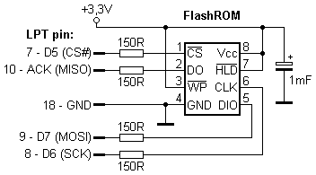
happy_bunny,
I am interested in flashing the board with your program "fpga_flash.exe" via parallel port and I couldn't find anyone to ask about it. I have got an old PC with parallel port and I have finally found few schematics. Would you tell me is this the right way to program the board, thanks.
Spoiler
Show
- Attachments
-
- simple_diagram.jpg
- (80.92 KiB) Not downloaded yet
-
- 3117_original.png
- (2.06 KiB) Not downloaded yet
-
happy_bunny
- Posts: 106
- Joined: Mon Mar 09, 2015 10:57 pm
Re: Shuriken Video
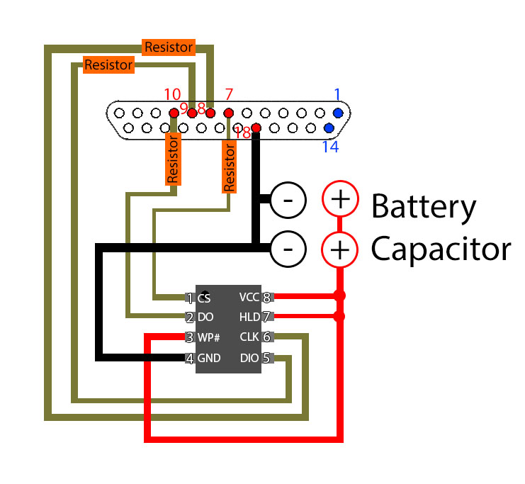
if you want to flash the chips before you put them on the pcb you will need something like this
however if you are programming them after they have been placed on the pcb you dont need to supply power
nice to meet someone that still has a parallel port although my old pc is almost dead video cards starting to die.
however if you are programming them after they have been placed on the pcb you dont need to supply power
nice to meet someone that still has a parallel port
Re: Shuriken Video
Thank you again.
I think there is a cheap solution for people without parallel ports. They can buy cheap programmer (CH341A) which can write "spi_flash.bin" to M25P40, after that build the board and test. Will this work or I am missing something?
I think there is a cheap solution for people without parallel ports. They can buy cheap programmer (CH341A) which can write "spi_flash.bin" to M25P40, after that build the board and test. Will this work or I am missing something?
-
marcus9199
- Posts: 141
- Joined: Fri Mar 28, 2014 5:43 am
- Location: Texas
Re: Shuriken Video
Finally got mine going! Man I have to say the hardest part was trying to program it on win 10. I had to substitute the 4.7 uf cap for a through hole one. I didn't see a voltage rating in the schematic. But apparently 10v was not enough I kept smoking them. This is a 35v.
- Attachments
-
- IMG_20151111_184330.jpg
- (1.1 MiB) Not downloaded yet
-
- IMG_20151111_184350.jpg
- (1.67 MiB) Not downloaded yet
My wife took my Beer Away!!!!
-
happy_bunny
- Posts: 106
- Joined: Mon Mar 09, 2015 10:57 pm
Re: Shuriken Video
@TALANTO
may buy that cheap programmer see if it works
@marcus9199
you sure you had the input cap the right way round, 10V should have been enough having said that I think the ones I have are 16 volt.
got the v3 boards today have not got a clue if they work need to check at the weekend but heres a pic
may buy that cheap programmer see if it works
@marcus9199
you sure you had the input cap the right way round, 10V should have been enough having said that I think the ones I have are 16 volt.
got the v3 boards today have not got a clue if they work need to check at the weekend but heres a pic