
XenoFUSION:
What do you get when you cross a Xeno GC modchip and a WKF? a XenoFUSION
The Atmega8 on the Xeno modchip has built in ADC functionality to monitor for voltage.
Using this feature to monitor the WKF SD card slot will allow the Xeno to also act as the pin29 switch to create an auto-load type functionality at bootup and can also be connected to your existing pin29 switch as backup (if needed).
This modification requires nothing more than 2 wire soldered and a XenoGC firmware update.
( is this the first ever unofficial firmware release? )
view MEGAdrive and XenoFUSION in action here http://www.youtube.com/watch?v=L-7U0fu-z3o
Code: Select all
Xeno will be set up to deliver GND signal on PortD to WKF.
Xeno will be set up to monitor voltage on PortC pin PC2.
   IF voltage is detected, PortD will shift to open GND.
      This will mimic pin 29 manual push switch functions and
      enable auto-loading of WKF iso.
   IF voltage is NOT detected, then PortD will remain as closed
      GND to allow normal DVD loading. Xeno drivecode will also
      upload as normal.
   IF voltage is detected once again after drivecode upload, then
      an SD Card must have been reinserted into the slot and an
      open GND signal will once again be sent to WKF pin 29.
Code: Select all
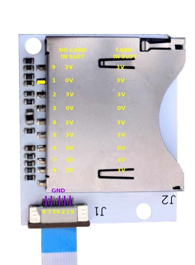
VOLTAGE MONITORING: is measured by a single wire between Atmega8 and the WKF SD card slot.
   WKF SD CARD PINOUT = 9, 1, 2, 3, 4, 5, 6, 7, 8
   WKF SD CARD Slot pin #1 = 0v when no card inserted.
   WKF SD CARD Slot pin #1 = 3v when card is inserted.
   Atmega8 pin PC2 is set up to monitor presence of voltage.
   Atmega8 pin PD5 is set up to provide pin29 GND function.
   A normally closed switch can also be used inline between
      the Atmega8 pin PD5 and the WKF pin29.  This will allow
      manual operation to "eject" the iso any time after
      automatic operation has been performed or to provide
      backup functionality for any reason undiscovered at
this point.http://www.gc-forever.com/wiki/index.ph ... eno_Fusion
installation
Code: Select all
2 wires
one solder bridge
It also happens to be the bottom left corner pin can be dedicated for voltage monitoring...luck!!
this bottom left corner pin is soldered to the WKF SD card slot pin #1 as indicated in the pic below.
the top right pin goes to WKF pin 29 or a normally closed switch (for backup purpose).
ELECTRICAL SAFETY NOTE: If you already have a pin29 switch, you must disconnect the lead from GND and solder it to Xeno instead.
DO NOT leave the switch soldered to GND and Xeno at the same time.
also, as shown in the pic, a solder bridge must be created between the "AREF" pin and the capacitor. This AREF pin is used as voltage reference for internal baseline voltage monitoring.